Mitsubishi Montero (2002-2004). Manual - part 110
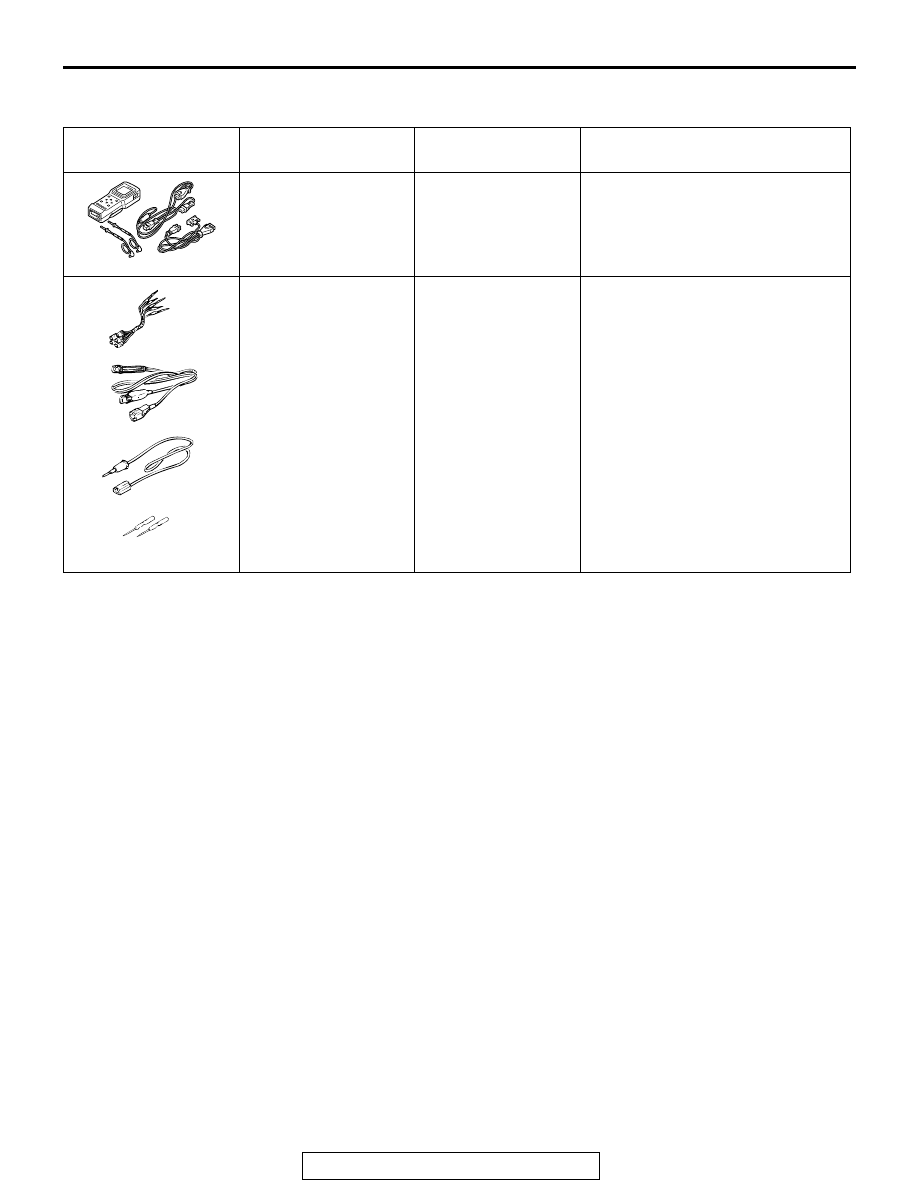
SPECIAL TOOLS
TSB Revision
AUTOMATIC AIR CONDITIONING
55B-133
SPECIAL TOOLS
M1554000600028
ON-VEHICLE SERVICE
CHARGING
M1552001200049
Use the refrigerant recovery station to charge the refrigerant.
METHOD BY USING REFRIGERANT RECOVERY
AND RECYCLING UNIT
Using the refrigerant recovery and recycling unit, refill the
refrigerant.
NOTE: Refer to the Refrigerant Recovery and Recycling Unit
Instruction Manual for operation of the unit.
DISCHARGING SYSTEM
Use the refrigerant recovery unit to discharge refrigerant gas
from the system.
NOTE: Refer to the Refrigerant Recovery and Recycling Unit
Instruction Manual for operation of the unit.
TOOL
TOOL NUMBER AND
NAME
SUPERSESSION
APPLICATION
MB991502 Scan tool
(MUT-II)
MB991496-OD
Diagnostic trouble code check
MB991223
Harness set
A: Connector pin
contact pressure
check
B: Power circuit check
C: Power circuit check
D: Commercial tester
connection
MB991223
MB991709-01
Continuity check and voltage
measurement at the harness
connector
A: Connector pin contact pressure
check
B: Power circuit check
C: Power circuit check
D: Commercial tester connection
B991502
MB991223
A
AB
B
C
D