Content .. 1086 1087 1088 1089 ..
Mitsubishi Montero (2002-2004). Manual - part 1088
STARTING SYSTEM
TSB Revision
ENGINE ELECTRICAL
16-25
INSPECTION
M1162001300049
.
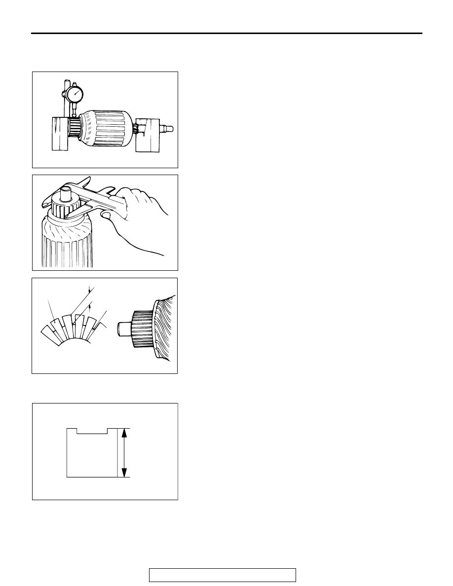
COMMUTATOR CHECK
1. Place the armature on a pair of V-blocks, and check the
deflection by using a dial gauge.
Standard value: 0.05 mm (0.002 inch)
Limit: 0.1 mm (0.004 inch)
2. Check the outer diameter of the commutator.
Standard value: 29.4 mm (1.16 inches)
Minimum limit: 28.8 mm (1.13 inches)
3. Check the depth of the undercut between segments.
Standard value: 0.5 mm (0.02 inch)
Minimum limit: 0.2 mm (0.008 inch)
.
BRUSH CHECK
1. Check the brush for roughness of the surface that contacts
the commutator and check the brush length.Replace the
brush holder if this measurement exceeds the limit.
Minimum limit: 7.0 mm (0.28 inch)
2. .In the case contacting surface has been corrected or the
brush has been replaced, correct the contacting surface by
winding sandpaper around the commutator
.
AKX00373
AKX00374
AKX00375
SEGMENT
UNDERCUT
MICA
AB
AK101390
LIMIT LENGTH
AB