Content .. 1059 1060 1061 1062 ..
Mitsubishi Montero (2002-2004). Manual - part 1061
ANTI-LOCK BRAKING SYSTEM (ABS) DIAGNOSIS
TSB Revision
ANTI-LOCK BRAKING SYSTEM (ABS)
35B-115
CHECK AT M-ASTC-ECU
M1352011800402
TERMINAL VOLTAGE CHECK CHART
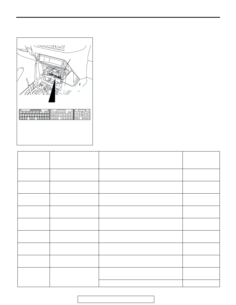
NOTE: There are two ECUs with the same shape inside the
floor console, one above the other. The upper ECU is the M-
ASTC-ECU. The lower ECU is the transfer-ECU.
NOTE: Do not measure terminal voltage for approximately
three seconds after the ignition switch is turned "ON." The M-
ASTC-ECU performs the initial check during that period.
1. Measure the voltages between terminals (4), (12), (56) or
(64) (ground terminals) and each respective terminal.
2. The terminal layouts are shown in the illustrations.
AC203901
AC204627AY
M-ASTC-ECU
M-ASTC-ECU CONNECTORS
TRANSFER-ECU
CONNECTOR
TERMINAL
NO.
SIGNAL
CHECKING REQUIREMENT
NORMAL
CONDITION
1
Control solenoid valve
OUT (Rear right wheel)
Ignition switch: ON
Battery positive
voltage
2
Control solenoid valve IN
(Rear right wheel)
Ignition switch: ON
Battery positive
voltage
3
Control solenoid valve
OUT (Front left wheel)
Ignition switch: ON
Battery positive
voltage
5
PI valve
Ignition switch: ON
Battery positive
voltage
6
Cut valve
Ignition switch: ON
Battery positive
voltage
7
Select solenoid valve
(Front right wheel)
Ignition switch: ON
Battery positive
voltage
8
Select solenoid valve
(Front left wheel)
Ignition switch: ON
Battery positive
voltage
10
Control solenoid valve IN
(Front left wheel)
Ignition switch: ON
Battery positive
voltage
19
Stoplight switch input
Stoplight switch: ON
Battery positive
voltage
Stoplight switch: OFF
2 V or less