Content .. 1057 1058 1059 1060 ..
Mitsubishi Montero (2002-2004). Manual - part 1059
ANTI-LOCK BRAKING SYSTEM (ABS) DIAGNOSIS
TSB Revision
ANTI-LOCK BRAKING SYSTEM (ABS)
35B-107
.
CIRCUIT OPERATION
• The ABS warning light power is supplied from the
ignition switch. The M-ASTC-ECU grounds the
circuit to illuminate the light. The light also illumi-
nates when the valve relay is switched to OFF.
• The M-ASTC-ECU illuminates the ABS warning
light for three seconds while running self-check.
This light can be illuminated for three seconds
upon start-up or ignition switch to the "ON" posi-
tion, engine stopped. The M-ASTC-ECU drives
the valve relay in the order of OFF to ON to OFF
to ON during initial check to check the valve relay.
.
TECHNICAL DESCRIPTION (COMMENT)
The M-ASTC-ECU causes the ABS warning light to
illuminate during the initial check (three seconds).
During the initial check, the valve relay turns from off
to on, off and back to on again, and if there is a open
circuit in the harness between the M-ASTC-ECU and
the ABS warning light, the light will illuminate only
when the valve relay is OFF because of a valve relay
test, etc.
.
TROUBLESHOOTING HINTS
• Damaged wiring harness or connector
• Malfunction of the M-ASTC-ECU
.
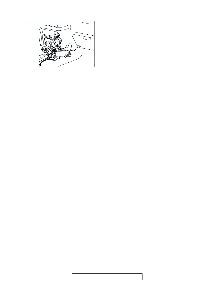
AC204385
CONNECTORS: E-108, E-110
AE
E-110
E-108(B)