Mitsubishi Montero (2002-2004). Manual - part 1062


  Index      Mitsubishi     Mitsubishi Montero - service repair manual 2002-2004 year


Search            


Content   ..  1060  1061  1062  1063   ..


Mitsubishi Montero (2002-2004). Manual - part 1062


ON-VEHICLE SERVICE

TSB Revision

ANTI-LOCK BRAKING SYSTEM (ABS)

35B-119

ON-VEHICLE SERVICE

ABS SENSOR OUTPUT VOLTAGE CHECK

M1352001600333

Required Special Tool:

• MB991219: Inspection Harness

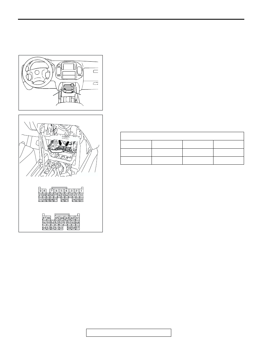
NOTE: Two ECUs of the same type are situated up and down 
in a row at the inner part of the floor console. The upper side 
ECU is the M-ASTC-ECU. The lower side ECU is the transfer 
ECU.
1. Lift up the vehicle and release the parking brake.

2. Disconnect the M-ASTC-ECU connector, and then use 

special tool MB991219 to measure the output voltage at the 
harness side connector.

3. Manually turn the wheel to be measured 1/2 to 1 turn/

second. Measure the output voltage with a voltmeter or 
oscilloscope.

Output voltage:

• Minimal voltmeter reading: 42 mV

• Maximum voltmeter reading: 300 mV

• Minimal oscilloscope reading: 120 mV

• Maximum oscilloscope reading: 600 mV

Probable causes of low output voltage

• ABS sensor pole piece-to-ABS rotor clearance too large

• Faulty ABS sensor

NOTE: Check the connection of the sensor harness and con-
nector before using the oscilloscope.

TERMINAL NO.

Front left

Front right

Rear left

Rear right

30

27

46

60

31

28

47

61

AC204258AB

M-ASTC-ECU

TRANSFER
-ECU

AC204264 AB

E-119

E-120

E-119 HARNESS CONNECTOR:
COMPNENT SIDE

E-120 HARNESS CONNECTOR:
COMPNENT SIDE

ON-VEHICLE SERVICE

TSB Revision

ANTI-LOCK BRAKING SYSTEM (ABS)

35B-120

4. To observe the waveform with an oscilloscope: Start the 

engine, move the transfer selector lever to the "4H" position 
and the transmission selector lever to "D" range, and then 
spin the wheel.
NOTE: The output waveform is low when the wheel speed is 
low. Similarly, it will be higher as the wheel speed increases. 
Waveform may also be observed by driving the vehicle.

.

POINTS IN WAVEFORM MEASUREMENT

NOTE: The ABS sensor cable moves in relation to motion of the front or rear suspension. Therefore, it is 
likely that it has an open circuit only when driving on rough roads but it functions normally when driving on 
smooth roads. It is recommended to observe sensor output voltage waveform also under special conditions, 
such as driving on a rough road.

ACX01114AB

WHEN TURNING BY HAND

WHEN IDLING [5 - 6 km/h (3 - 4 mph) ]
D RARGE (AUTOMATIC TRANSAXLE)

10.0 ms/DIV
1V/DIV

SYMPTOM

PROBABLE CAUSES

REMEDY

Too small or zero waveform 
amplitude

Faulty ABS sensor

Replace sensor

Waveform amplitude fluctuates 
excessively (This is no problem if 
the minimum amplitude is 100 mV 
or more)

Axle hub eccentric or with large 
runout

Replace hub

Noisy or disturbed waveform

Open circuit in ABS sensor

Replace sensor

Open circuit in harness

Repair harness

Incorrectly mounted ABS sensor

Mount correctly

ABS rotor with missing or 
damaged teeth

Replace ABS rotor

ON-VEHICLE SERVICE

TSB Revision

ANTI-LOCK BRAKING SYSTEM (ABS)

35B-121

ABS VALVE RELAY CHECK

M1352010900127

HYDRAULIC BRAKE BOOSTER (HBB) 
HYDRAULIC UNIT CHECK

M1352001700341

Required Special Tool:

• MB991502: Scan Tool (MUT-II)

CAUTION

• The roller of the braking force tester and the tire should 

be dry during testing.

• When testing the front brakes, apply the parking brake. 

When testing the rear brakes, stop the front wheels 
with chocks.

1. Jack up the vehicle. Then support the vehicle with rigid 

racks at the specified jack-up points or place the front or rear 
wheels on the rollers of the braking force tester.

2. Release the parking brake, and feel the drag force (drag 

torque) on each road wheel. When using the braking force 
tester, take a reading of the brake drag force.

BATTERY VOLTAGE

TESTER 
CONNECTION

SPECIFIED 
CONDITION

Not applied

− 4

Less than 2 
ohms

− 5

Open circuit

• Connect terminal 1 to the 

positive battery terminal

• Connect terminal 3 to the 

negative battery terminal

− 4

Open circuit

− 5

Less than 2 
ohms

AC204274

AB

VALVE RELAY

2

1

3

5

4

1

3

2

4
5

ON-VEHICLE SERVICE

TSB Revision

ANTI-LOCK BRAKING SYSTEM (ABS)

35B-122

CAUTION

To prevent damage to scan tool MB991502, always turn the 
ignition switch to the "LOCK" (OFF) position before con-
necting or disconnecting scan tool MB991502.
3.  Turn the ignition switch to the "LOCK" (OFF) position and 

set scan tool MB991502 as shown in the illustration.

4. After checking that the selector lever is in neutral, start the 

engine.

5. Use scan tool MB991502 to force-drive the actuator.

NOTE: The ABS system will switch to the scan tool mode 
and the ABS warning light will illuminate.
NOTE: When the ABS has been interrupted by the fail-safe 
function, scan tool MB991502 actuator testing cannot be 
used.

6. Turn the wheel by hand and check the change in braking 

force when the brake pedal is depressed. When using the 
braking force tester, depress the brake pedal until the 
braking force is at the following values, and check that the 
braking force changes to the brake drag force instep 2 when 
the actuator is force-driven.The result should be as shown in 
the diagram above.

Front wheel: 785 

 981 N (176  220 lb)

Rear wheel: 785 

 981 N (176  220 lb)

7. If the result of inspection is abnormal, repair according to the 

Diagnosis Table below.

ACX01539AE

MB991502

16-PIN

ACX01115 AB

INCREASE IN PRESSURE

STEADY PRESSURE

SCAN TOOL ACTUATOR TEST (ITEM No. 01, 02, 03, 04) START

REDUCTION IN PRESSURE 
(WHEN NOT WORKING)

PEDAL
OPERATION

SOLENOID VALVE 
POSITION

CHECKING THE
BRAKE FORCE

DEPRESSED

RELEASED

1 s

2 s

LOCK
DRAG FORCE WHEN 
PEDAL IS RELEASED


Content   ..  1060  1061  1062  1063   ..