Mitsubishi Montero (1998+). Manual - part 33


  Index      Mitsubishi     Mitsubishi Montero - service repair manual 1998 year


Search            


Content   ..  31  32  33  34   ..


Mitsubishi Montero (1998+). Manual - part 33


         ADJUSTMENTS

         * PLEASE READ FIRST *

NOTE:    For adjustment information on brake pedal height, free play,

         parking brake and stoplight switch, see BRAKE SYSTEM article.

         WHEEL SPEED SENSOR (WSS)

NOTE:    Rear WSS gap adjustment information is not available from

         manufacturer.

         Front WSS-To-Rotor Gap Adjustment

         1) Raise and support vehicle. Remove wheel(s). Inspect sensor

pole piece for damage. Repair if necessary. If sensor pole piece is

okay, check WSS-to-rotor gap.

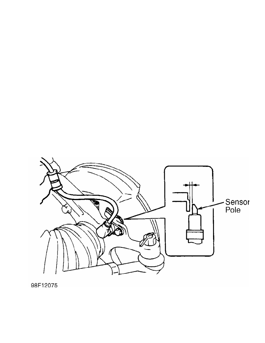
         2) Using a feeler gauge, check clearance between sensor pole

and rotor tooth surface. See Fig. 1. Front WSS sensor clearance should

be .008-.390" (0.2-1.0 mm). If clearance is not as specified, loosen

sensor mounting bolt. Adjust sensor position until clearance is within

specification. Tighten sensor mounting bolt to specification. See

TORQUE SPECIFICATIONS.

Fig. 1:  Checking Front WSS-To-Rotor Gap

Courtesy of Mitsubishi Motor Sales of America.

         TROUBLE SHOOTING

         ANTI-LOCK WARNING LIGHT

         1) Turn ignition on. ANTI-LOCK warning light should come on

for one second, and then go out. Turn ignition switch to START

position. Warning light should come on and stay on.

         2) When ignition switch is turned from START to ON position,

warning light should come on for one second, and then go out. If

warning light functions as specified, go to step 3). If warning light

does not function as specified, see appropriate trouble shooting test:

      *  IGNITION SWITCH IN ON POSITION (ENGINE NOT RUNNING),

         ANTI-LOCK WARNING LIGHT INOPERATIVE

      *  AFTER ENGINE STARTS, ANTI-LOCK WARNING LIGHT REMAINS ON

      *  IGNITION SWITCH IN START POSITION, ANTI-LOCK WARNING LIGHT

         INOPERATIVE

      *  IGNITION SWITCH IN ON POSITION, ANTI-LOCK WARNING LIGHT

         BLINKS TWICE. IN START POSITION, LIGHT STAYS ON. WHEN

         IGNITION SWITCH IS CYCLED FROM START TO ON POSITION, LIGHT

         BLINKS ONCE, THEN TURNS OFF

         3) Test drive vehicle. If ANTI-LOCK warning light does not

come on at low speed, go to next step. If light comes on at low speed,

motor relay, solenoid valve or Wheel Speed Sensor (WSS) malfunction is

indicated. Go to step 6). If insufficient braking force or ABS

malfunction exists, go to next step. If none of listed symptoms exist,

go to step 6).

         4) Check conventional brake system components for proper

operation. Check for mechanical lock of hydraulic unit solenoid valve.

Check for plugged hydraulic line in hydraulic unit. Repair or replace

as necessary. If hydraulic unit is okay, go to next step.

         5) Ensure WSS rotor gap is correct. See WHEEL SPEED SENSOR

(WSS) under ADJUSTMENTS. Check for faulty wheel speed sensor. See

WHEEL SPEED SENSOR (WSS) under COMPONENT TESTS. Replace sensor as

necessary. See WHEEL SPEED SENSOR (WSS) under  REMOVAL & INSTALLATION.

Inspect ECU connectors and related wiring harness. See  WIRING DIAGRAMS

. If testing indicates no mechanical or electrical failures,

substitute ECU with known-good unit and retest.

         6) Enter ABS self-diagnostics and retrieve Diagnostic Trouble

Codes (DTCs). See RETRIEVING DTCs under SELF-DIAGNOSTIC SYSTEM. If no

DTCs are displayed, fault may be intermittent. Attempt to make

malfunction reoccur. If no diagnostic output exists, check and repair

wiring harness between ECU and data link connector. See

WIRING DIAGRAMS.

NOTE:    Trouble shoot ANTI-LOCK warning light in following sequence:

         instrument cluster circuit, ECU and valve relay.

         Ignition Switch In ON position (Engine Not Running),

         ANTI-LOCK Warning Light Inoperative

         1) If all other warning lights come on with ignition on, go

to step 3). If other warning lights do not come on, check fuse No. 11

in main fuse panel. If fuse is blown, correct cause of blown fuse, and

replace fuse. If fuse is okay, go to next step.

         2) Remove instrument cluster. Turn ignition on. Using DVOM,

check voltage between vehicle ground and instrument cluster ANTI-LOCK

warning light terminal No. 28. See Fig. 2. If light does not come on,

go to next step. If light comes on, check and repair connectors and

related wiring harness between instrument cluster, ABS valve relay and

ECU. See WIRING DIAGRAMS.

         3) Turn ignition off. Check for faulty warning light bulb.

Replace bulb as necessary. If bulb is okay, check and repair

connectors and related wiring harness between instrument cluster and

ECU. See WIRING DIAGRAMS. If connectors and wiring are okay, replace

instrument cluster.

Fig. 2:  Identifying Instrument Cluster Connector Terminals

Courtesy of Mitsubishi Motor Sales of America.

         After Engine Starts, ANTI-LOCK Warning Light Remains On

         1) With ignition on, disconnect instrument cluster

connectors. If warning light remains on, replace instrument cluster.

If warning light goes off, go to next step.

         2) Disconnect ECU 22-pin connector and ABS relay box 8-pin

connector. See Fig. 3. If warning light goes off, replace ECU. If

warning light stays on, check and repair connectors and related wiring

harness between ECU, instrument cluster, and ABS valve relay. See

WIRING DIAGRAMS.

Fig. 3:  Exploded View Of Hydraulic Unit & Components

Courtesy of Mitsubishi Motor Sales of America.

         Ignition Switch In START Position, ANTI-LOCK Warning Light

         Inoperative

         1) Inspect ABS relay box. See Fig. 3. Replace ABS relay box

if needed. If ABS relay box is okay, go to next step.

         2) Disconnect ECU 22-pin connector and ABS relay box 8-pin

connector. Turn ignition on. Using a DVOM, check voltage between ABS

relay box 8-pin harness connector terminal No. 5 and ground. See

Fig. 4. If battery voltage does not exist, go to next step. If battery

voltage exists, check and repair connectors and related wiring harness

between ABS valve relay and ground. See WIRING DIAGRAMS.

         3) Check and repair connectors and related wiring harness

between instrument cluster and ABS valve relay. See  WIRING DIAGRAMS.

Fig. 4:  Identifying ABS Relay Box Connector Terminals

Courtesy of Mitsubishi Motor Sales of America.

         Ignition Switch In ON Position, ANTI-LOCK Warning Light

         Blinks Twice. In START Position, Light Stays On. When

         Ignition Switch Is Cycled From START To ON Position, Light

         Blinks Once

         1) Disconnect ABS relay box connectors. See  Fig. 3.

Disconnect ECU 22-pin connector. Turn ignition on. Check voltage

between ECU connector terminal No. 50 and ground. See  Figs. 5-6. If

battery voltage is not present, check and repair connectors and

related wiring harness between instrument cluster and ECU. See

WIRING DIAGRAMS. If battery voltage is present, go to next step.

         2) Check and repair ECU 22-pin connector. If connector is

okay, replace ECU.


Content   ..  31  32  33  34   ..