Mitsubishi Galant (2004+). Manual - part 794


  Index      Mitsubishi     Mitsubishi Galant - service repair manual 2004 year


Search            


Content   ..  792  793  794  795   ..


Mitsubishi Galant (2004+). Manual - part 794


AUTO A/C DIAGNOSIS

TSB Revision

AUTOMATIC AIR CONDITIONING

55B-21

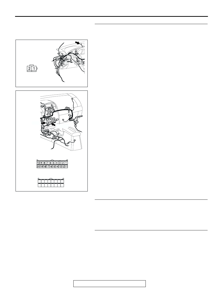
STEP 5. Check the wiring harness between photo sensor 
connector C-04 (terminal 1, 2) and A/C-ECU connector 
C-15 (terminal 19), C-16 (terminal 25).

Q: Is the wiring harness between photo sensor connector 

C-04 (terminal 1, 2) and A/C-ECU connector C-15 
(terminal 19), C-16 (terminal 25) in good condition?
YES : 
Go to Step 6.
NO :  Repair the wiring harness. Check that the air 

conditioning works normally.

STEP 6. Replace the photo sensor.
Q: Does the A/C operate normally?

YES : No action is necessary and testing is complete.
NO :  Replace the A/C-ECU. Check that the air conditioning 

works normally. 

STEP 7. Check the refrigerant level.

Use the refrigerant recovery station to remove all of the refrig-
erant, and then calculate the amount of the refrigerant and 
charge it.
Q: Is the refrigerant level correct?

YES : Refer to GROUP 55A, Symptom Chart 

P.55A-181

.

NO :  Correct the refrigerant level (Refer to GROUP 55A, 

On-vehicle Service 

P.55A-266

). Check that the air 

conditioning works normally. 

AC305231

CONNECTOR: C-04

CM

HARNESS SIDE

AC305234

CONNECTORS: C-15, C-16

C-16 (B)

HARNESS SIDE

C-16

C-15

C-15 (B)

HARNESS SIDE

21

22

23

24

25

26

27

28

29

30

31

32

33

34

35

36

AG

AUTO A/C DIAGNOSIS

TSB Revision

AUTOMATIC AIR CONDITIONING

55B-22

DATA LIST REFERENCE TABLE

M1554005100147

CHECK AT A/C-ECU TERMINAL

M1552010300572

SCAN TOOL 
(MUT-III) 
DISPLAY

ITEM 
NO.

INSPECTION ITEM INSPECTION REQUIREMENT

NORMAL VALUE

Inside 
temperature 
sensor

01

Interior temperature 
sensor

Ignition switch: ON

Inside air 
temperature and 
temperature 
displayed on the 
scan tool are 
identical.

Photo sensor

06

Photo sensor

Ignition switch: ON

Amount of light is 
proportional to 
voltage displayed on 
the scan tool.

8

2

1

5

3 4

6 7

9 10

20

19

18

17

16

15

14

13

12

11

32

24

29

21

31

30

2223

27

35

33

25

34

26

36

28

AC210339

C-15

C-16

AB

TERMINAL 
NO.

CHECK ITEM

CHECKING REQUIREMENTS NORMAL CONDITION

1

Air mixing damper control motor When the air mix damper is 

moved to the MAX. COOL 
position. 

10 V

When the air mix damper is 
moved to the MAX. HOT 
position. 

0.5 V

2

Air mixing damper control motor When the air mix damper is 

moved to the MAX. COOL 
position. 

0.5 V

When the air mix damper is 
moved to the MAX. HOT 
position. 

10 V

3

Back-up power supply

Always

Battery positive voltage

4

Mode selection damper control 
motor (DEF)

When the damper is moved to 
the FACE position. 

0.5 V

When the damper is moved to 
the DEF position. 

10 V

5

Outside/inside air selection 
damper control motor (outside)

When the damper is moved to 
the inside air recirculation 
position.

0.5 V

When the damper is moved to 
the outside air induction 
position.

0 V (when the motor is 
stopped)

AUTO A/C DIAGNOSIS

TSB Revision

AUTOMATIC AIR CONDITIONING

55B-23

6

Outside/inside air selection 
damper control motor (inside)

When the damper is moved to 
the inside air recirculation 
position.

0 V (when the motor is 
stopped)

When the damper is moved to 
the outside air induction 
position.

0.5 V

8

Rear defogger relay

Ignition switch: ON

Battery positive voltage

9

Front blower relay

Ignition switch: ON

Battery positive voltage

10

A/C compressor relay

A/C compressor relay: ON

Battery positive voltage

11

Mode selection damper control 
motor (FACE)

When the damper is moved to 
the FACE position. 

10 V

When the damper is moved to 
the DEF position. 

0.5 V

12

A/C pressure sensor

Ignition switch: ON

5 V

16

Potentiometer power supply

Ignition switch: ON

5 V

17

Power transistor (BASE)

When the blower speed 
selection dial shows Maximum 
air volume.

1 V

18

Power transistor 
(COLLECTOR)

When the blower speed 
selection dial shows Maximum 
air volume.

12.1 V

19

Photo sensor

Ignition switch: ON

5 V

20

Sensors and potentiometers 
ground

Always

0 V

21

Mode selection damper control 
motor potentiometer input

When the damper is moved to 
the FACE position. 

4 V

22

Interior temperature sensor

Ignition switch: ON

5 V

23

Ambient temperature sensor 
input

When sensor temperature is 
25

°C (77°F) [4 kΩ]

1.9 V

24

Air thermo sensor input

When sensor temperature is 
25

°C (77°F) [1.5 kΩ]

2.2 V

25

Photo sensor ground

Ignition switch: ON

0 V

26

A/C pressure sensor

at 2.6 MPa

3.9 V

27

Ground

Always

0 V

28

Power supply to the ignition 
switch (IG2)

Ignition switch: ON

Battery positive voltage

29

Air mixing damper control motor 
potentiometer input

When the damper door is 
moved to the MAX. HOT 
position.

1.4 V

30

Illumination ground

Always

0 V

31

ILL power supply

Lighting switch: ON

Battery positive voltage

34

A/C pressure sensor ground

Always

0 V

36

Power supply to the ignition 
switch (ACC)

Ignition switch: ON

Battery positive voltage

TERMINAL 
NO.

CHECK ITEM

CHECKING REQUIREMENTS NORMAL CONDITION

SPECIAL TOOLS

TSB Revision

AUTOMATIC AIR CONDITIONING

55B-24

SPECIAL TOOLS

M1552000600345

TOOL

TOOL NUMBER 
AND NAME

SUPER SESSION APPLICATION

MB991958
A: MB991824
B: MB991827
C: MB991910
D: MB991911
E: MB991914
F: MB991825
G: MB991826
MUT-III Sub 
Assembly
A: Vehicle 
Communication 
Interface (V.C.I)
B: MUT-III USB 
Cable
C: MUT-III Main 
Harness A 
(Vehicles with CAN 
communication 
system)
D: MUT-III Main 
Harness B 
(Vehicles without 
CAN 
communication 
system)
E: MUT-III Main 
Harness C (for 
Chrysler models 
only)
F: MUT-III Adapter 
Harness
G: MUT-III Trigger 
Harness

MB991824-KIT
NOTE: G: 
MB991826 MUT-III 
Trigger Harness is 
not necessary 
when pushing 
V.C.I. ENTER key.

Checking diagnostic trouble codes

CAUTION

For vehicles with CAN 
communication, use MUT-III 
main harness A to send 
simulated vehicle speed. If you 
connect MUT-III main harness B 
instead, the CAN communication 
does not function correctly.

MB991910

MB991826

MB991958

MB991911

MB991914

MB991824

MB991827

MB991825

DO NOT USE

A

B

C

D

E

F

G

DO NOT USE


Content   ..  792  793  794  795   ..