Mitsubishi Galant (2004+). Manual - part 708


  Index      Mitsubishi     Mitsubishi Galant - service repair manual 2004 year


Search            


Content   ..  706  707  708  709   ..


Mitsubishi Galant (2004+). Manual - part 708


ON-VEHICLE SERVICE

TSB Revision

AUTOMATIC TRANSAXLE

23A-383

(4) Loosen the bolt fixing the shift lock cable unit, push the 

lever in direction B and the unit in direction C and tighten 
the bolt at the standard torque.

Tightening torque: 5.0 

± 1.0 Nm (44 ± 9 in-lb)

(5) Lift the lock guide of the key interlock cable and then 

unlock it.

(6) Lower the lock guide of the key interlock cable and then 

lock it.
NOTE: The key interlock cable is adjusted according to 
the lock position (cap push state) at this time. Readjust 
the lock position if key interlocking operations malfunction 
after locking.

3. After adjustment, re-check the operations. Replace the key 

interlock cable and shift lock cable unit if operations are 
defective. (Refer to 

P.23A-389

).

TRANSAXLE CONTROL CABLE ADJUSTMENT

M1231028000064

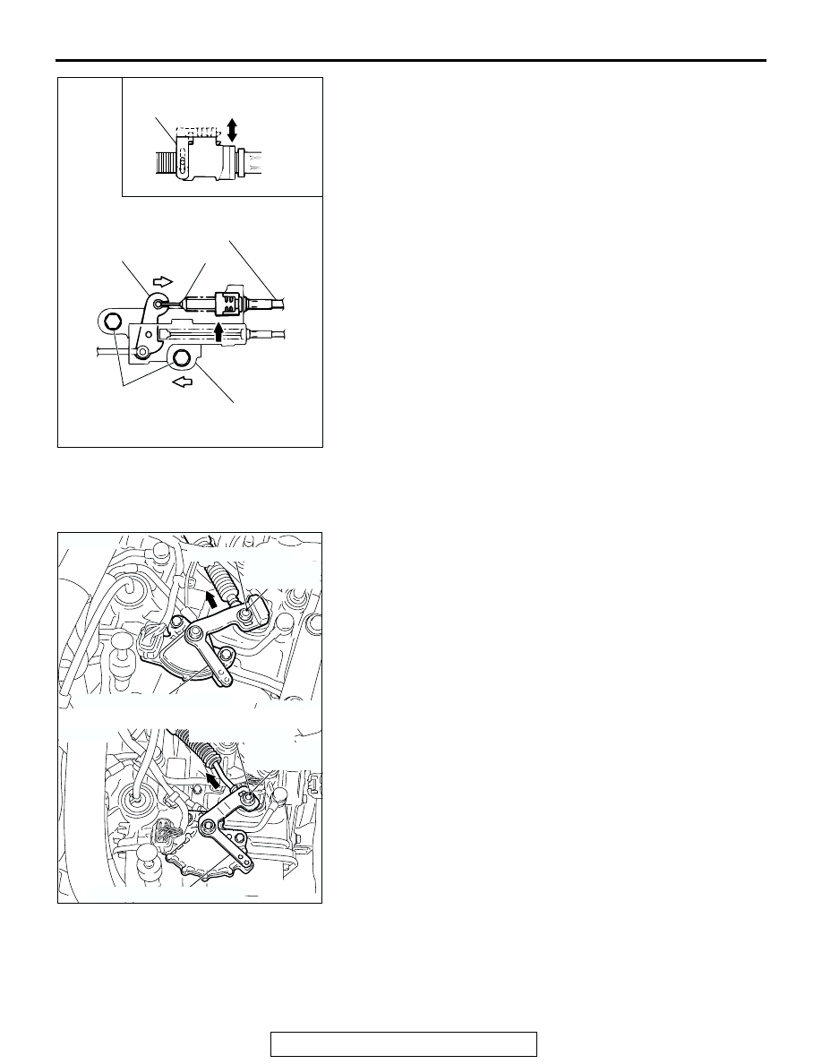
1. Move the selector lever to the "N" position.
2. Loosen the upper control lever adjusting nut.
3. Gently push the transaxle control cable in the direction of the 

arrow, and then tighten the adjusting nut.

Tightening torque: 12 

± 2 Nm (107 ± 17 in-lb)

4. Check that the transaxle shifts to the correct range 

corresponding to the position of the selector lever, and that it 
functions correctly in that range.

AC000004AG

LOCK

UNLOCK

LOCK GUIDE

KEY INTERLOCK CABLE

CAP

LEVER

FIXING BOLT

SHIFT LOCK CABLE UNIT

C

A

B

VIEW A

AC305881

AC305532

AC305679

<F4A4B>

MANUAL CONTROL LEVER

MANUAL CONTROL LEVER

<F4A5A>

ADJUSTING NUT

12 ± 2 N·m
107 ± 17 in-lb

ADJUSTING NUT

12 ± 2 N·m
107 ± 17 in-lb

AE

TRANSAXLE CONTROL

TSB Revision

AUTOMATIC TRANSAXLE

23A-384

TRANSAXLE CONTROL

REMOVAL AND INSTALLATION

M1231006600369

WARNING

When removing and installing the transaxle control cable and shift lock cable unit, be 
careful not to hit the SRS-ECU.

When removing and installing the front passenger seat, be sure to carry out accuracy 
check occupant classification sensor after the seat has been installed in the vehicle. 
(Refer to GROUP 52B, On-Vehicle Service 

P.52B-354

.)

AC305533AB

1

12 ± 2 N·m
107 ± 17 in-lb

<F4A5A>

<F4A4B>

2

2

5

6

8

3

12 ± 2 N·m
102 ± 22 in-lb

5.0 ± 1.0 N·m
44 ± 9 in-lb

12 ± 2 N·m
102 ± 22 in-lb

4

7

7

TRANSAXLE CONTROL 
CABLE ASSEMBLY REMOVAL 
STEPS

AIR DUCT AND AIR CLEANER 
ASSEMBLY (REFER TO GROUP 
15 

P.15-4

.)

BATTERY AND BATTERY TRAY

POWERTRAIN CONTROL 
MODULE (PCM) (REFER TO 
GROUP 13A 

P.13A-1121

.)

HEATER UNIT AND DECK 
CROSSMEMBER ASSEMBLY 
(REFER TO GROUP 55, 
HEATER UNIT, HEATER CORE, 
BLOWER ASSEMBLY AND 
EVAPORATOR UNIT 

P.55A-271

.)

>>B<<

1.

ADJUSTING NUT

>>B<<

2.

TRANSAXLE CONTROL CABLE 
ASSEMBLY CONNECTION 
(TRANSAXLE SIDE)

>>A<<

3.

SHIFT LOCK CABLE UNIT

4.

TRANSAXLE CONTROL CABLE 
ASSEMBLY CONNECTION 
(SELECTOR LEVER ASSEMBLY 
SIDE)

5.

TRANSAXLE CONTROL CABLE 
ASSEMBLY
SELECTOR LEVER ASSEMBLY 
ASSEMBLY REMOVAL STEPS

FLOOR CONSOLE (REFER TO 
GROUP 52A, FLOOR CONSOL 
ASSEMBL

P.52A-9

)

>>A<<

3.

SHIFT LOCK CABLE UNIT

4.

TRANSAXLE CONTROL CABLE 
ASSEMBLY CONNECTION 
(SELECTOR LEVER ASSEMBLY 
SIDE)

TRANSAXLE CONTROL 
CABLE ASSEMBLY REMOVAL 
STEPS (Continued)

TRANSAXLE CONTROL

TSB Revision

AUTOMATIC TRANSAXLE

23A-385

INSTALLATION SERVICE POINTS

.

>>A<< SHIFT LOCK CABLE UNIT INSTALLATION
1. Selector lever to "P" position.
2. Turn the ignition key to "LOCK" (OFF) position.
3. Install the rod of the shift lock cable unit to the lock cam, 

push the lever in direction A, push the shift lock cable unit in 
direction B and tighten the bolt at the standard torque.

Tightening torque: 5.0 

± 1.0 Nm (44 ± 9 in-lb)

4. Check the selector lever operation.(Refer to 

P.23A-381

).

.

>>B<< ADJUSTING NUT/TRANSAXLE CONTROL CABLE 
(TRANSAXLE SIDE) INSTALLATION
1. Place the selector lever and manual control lever in the "N" 

position.

2. Place the cable stud into the manual control lever slot and 

install the nut loosely. Gently push the transaxle control 
cable into the manual control lever slot until the cable is taut. 
Tighten the nut to the specified torque.

Tightening torque: 12 

± 2 Nm (107 ± 17 in-lb)

6.

A/T SELECTOR LEVER POSITION 
ILLUMINATION LIGHT HARNESS 
CONNECTOR <VEHICLES 
WITHOUT SPORT MODE>, 
SHIFT SWITCH ASSEMBLY 
HARNESS CONNECTOR 
<VEHICLES WITH SPORT 
MODE>

7.

HARNESS CILP CONNECTION

8.

SELECTOR LEVER ASSEMBLY

SELECTOR LEVER ASSEMBLY 
ASSEMBLY REMOVAL STEPS 

AC308762

SHIFT LOCK 
CABLE UNIT

AB

LOCK CAM

LEVER

BOLT

ROD

A

B

AC305881

AC305532

AC305679

<F4A4B>

MANUAL CONTROL LEVER

MANUAL CONTROL LEVER

<F4A5A>

ADJUSTING NUT

12 ± 2 N·m
107 ± 17 in-lb

ADJUSTING NUT

12 ± 2 N·m
107 ± 17 in-lb

AE

TRANSAXLE CONTROL

TSB Revision

AUTOMATIC TRANSAXLE

23A-386

INSPECTION

M1231030000094

Check the cable assembly for function and for damage.

 DISASSEMBLY AND ASSEMBLY

M1231006800363

<VEHICLES WITHOUT SPORT MODE>

AC306189

2

3

4

1

6

6

7

2.0 ± 0.3 N·m
18 ± 2 in-lb

AB

5

DISASSEMBLY STEPS

1.

SHIFT KNOB

2.

PUSH BUTTON

3.

SPRING

4.

INDICATOR PANEL

5.

A/T SELECTOR LEVER 
POSISITION ILLUMINATION 
LIGHT

6.

BRACKET STAY

7.

SHIFT LEVER ASSEMBLY

DISASSEMBLY STEPS 


Content   ..  706  707  708  709   ..