Mitsubishi Galant (2004+). Manual - part 709
TRANSAXLE CONTROL
TSB Revision
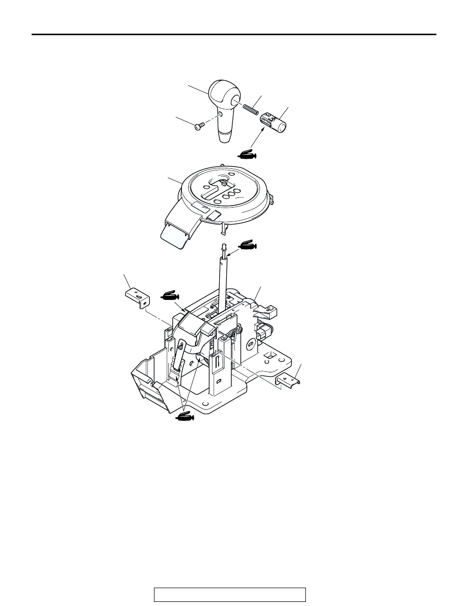
AUTOMATIC TRANSAXLE
23A-387
<VEHICLES WITH SPORT MODE>
AC305576
2
3
4
1
5
5
6
2.0 ± 0.3 N·m
18 ± 2 in-lb
AB
DISASSEMBLY STEPS
1.
SHIFT KNOB
2.
PUSH BUTTON
3.
SPRING
4.
INDICATOR PANEL
5.
BRACKET STAY
6.
SHIFT LEVER ASSEMBLY
DISASSEMBLY STEPS