Mitsubishi Galant (2004+). Manual - part 539


  Index      Mitsubishi     Mitsubishi Galant - service repair manual 2004 year


Search            


Content   ..  537  538  539  540   ..


Mitsubishi Galant (2004+). Manual - part 539


ANTI-LOCK BRAKING SYSTEM (ABS) DIAGNOSIS

TSB Revision

ANTI-LOCK BRAKING SYSTEM (ABS)

35B-101

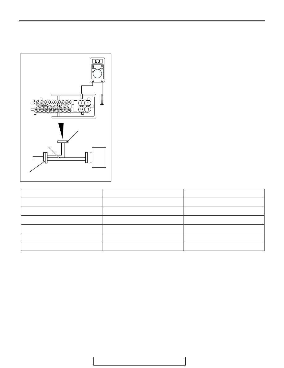
RESISTANCE AND CONTINUITY BETWEEN 
HARNESS-SIDE CONNECTOR TERMINALS

Required Special Tool:
MB991970: ABS Check Harness
1. Turn the ignition switch to the "LOCK" (OFF) position and 

disconnect the ABS-ECU connectors before checking 
resistance and continuity.

2. Check the resistance and continuity between the terminals 

indicated in the table below.

3. The terminal layout is shown in the illustration.

AC211160 AC

ABS-ECU

A-02 HARNESS CONNECTOR

MB991970

INSPECTION
HARNESS
CONNECTOR

CONNECTOR TERMINAL NO.

SIGNAL

NORMAL CONDITION

− 10

Front-right wheel speed sensor

1.24 

− 1.64 kΩ

11 

− 17

Rear-right wheel speed sensor

1.24 

− 1.64 kΩ

16 

− 26

Front-left wheel speed sensor

1.24 

− 1.64 kΩ

27 

− 28

Rear-left wheel speed sensor

1.24 

− 1.64 kΩ

− body ground

Ground

Less than 2 ohms

18 

− body ground

Ground

Less than 2 ohms

SPECIAL TOOLS

TSB Revision

ANTI-LOCK BRAKING SYSTEM (ABS)

35B-102

SPECIAL TOOLS

M1352000600653

TOOL

TOOL NUMBER AND NAME SUPERSESSION

APPLICATION

MB991958

A: MB991824
B: MB991827
C: MB991910
D: MB991911
E: MB991914
F: MB991825
G: MB991826

MUT-III Sub Assembly

A: Vehicle Communication 

Interface (V.C.I.)

B: MUT-III USB Cable
C: MUT-III Main Harness A 

(Vehicles with CAN 
communication system)

D: MUT-III Main Harness B 

(Vehicles without CAN 
communication system)

E: MUT-III Main Harness C 

(for Daimler Chrysler 
models only)

F: MUT-III Adapter Harness
G: MUT-III Trigger Harness

MB991824

−KIT

NOTE: G: MB991826 
MUT-III Trigger 
Harness is not 
necessary when 
pushing V.C.I. ENTER 
key.

Checking diagnostic 
trouble codes

CAUTION

For vehicles with CAN 
communication, use 
MUT-III main harness A 
to send simulated 
vehicle speed. If you 
connect MUT-III main 
harness B instead, the 
CAN communication 
does not function 
correctly.

MB991970 
ABS check harness

ABS-ECU terminal 
voltage measurement

MB991910

MB991826

MB991958

MB991911

MB991914

MB991824

MB991827

MB991825

DO NOT USE

A

B

C

D

E

F

G

DO NOT USE

MB991970

SPECIAL TOOLS

TSB Revision

ANTI-LOCK BRAKING SYSTEM (ABS)

35B-103

MB991223 
Harness set
 A: MB991219
 Inspection harness

General service tools

Wheel speed sensor 
output voltage 
measurement

TOOL

TOOL NUMBER AND NAME SUPERSESSION

APPLICATION

MB991223

A

AH

ON-VEHICLE SERVICE

TSB Revision

ANTI-LOCK BRAKING SYSTEM (ABS)

35B-104

ON-VEHICLE SERVICE

WHEEL SPEED SENSOR OUTPUT VOLTAGE 
MEASUREMENT

M1352001600526

Required Special Tool:
MB991219: Inspection Harness
1. Release the parking brake and lift up the vehicle.
2. Disconnect the ABS-ECU connector A-02, and then use 

special tool MB991219 to measure the output voltage at the 
harness side connector.

TERMINAL NO.

Front left

Front right

Rear left

Rear right

16

9

27

11

26

10

28

17

AC306403

19

2

18

1

8

9

7

6

5

4

3

10

11   

25

15

16

17

27

28

26

12

13

14

23

24

22 21 20

AD

ABS-ECU

MB991970

CHECK CONNECTOR

A-02 HARNESS
CONNECTOR

A-02 (GR)

CONNECTOR: A-02

HYDRAULIC UNIT
(WITH BUILT-IN ABS-ECU)


Content   ..  537  538  539  540   ..