Mitsubishi Galant (2004+). Manual - part 508


  Index      Mitsubishi     Mitsubishi Galant - service repair manual 2004 year


Search            


Content   ..  506  507  508  509   ..


Mitsubishi Galant (2004+). Manual - part 508


ON-VEHICLE SERVICE

TSB Revision

BASIC BRAKE SYSTEM

35A-19

CAUTION

Do not wipe off the special grease that is on the lock pin. 
Do not contaminate the lock pin.
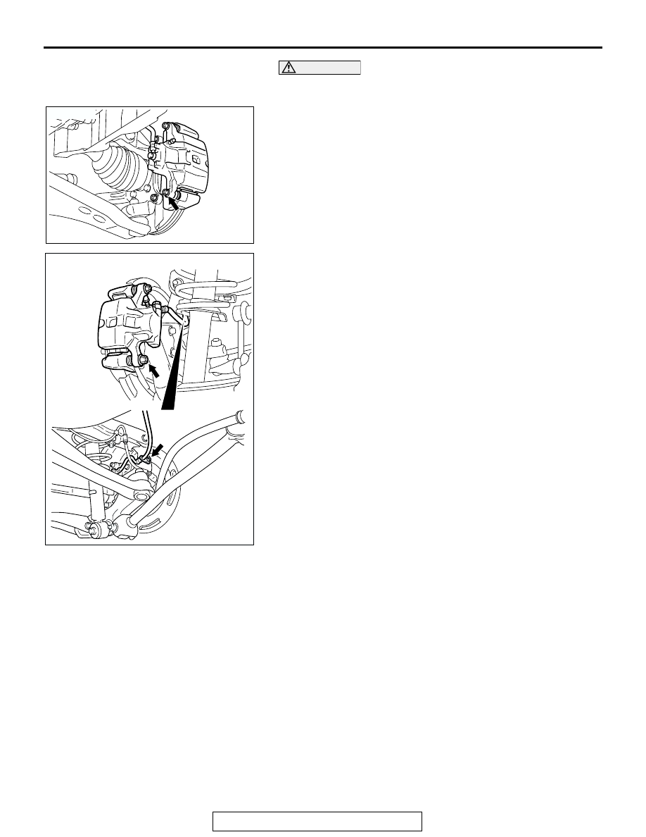
2. Remove the lock pin bolt <Front> or lock pin and brake hose 

clamp <Rear>. Pivot the caliper assembly and hold it with 
wires.

AC305371

AC

<FRONT>

AC307348

AB

<REAR>

ON-VEHICLE SERVICE

TSB Revision

BASIC BRAKE SYSTEM

35A-20

3. Remove the following parts from the caliper support.

(1) Pad assembly
(2) Pad and wear indicator assembly or Pad assembly 
(3) Shim
(4) Clip

4. In order to measure the brake drag force after pad 

installation, measure the rotary-sliding resistance of the hub 
with the pads removed (Refer to 

P.35A-30

).

5. Install the pads and caliper assembly, and then check the 

brake drag force (Refer to 

P.35A-30

).

DISC BRAKE ROTOR CHECK

M1351002900334

CAUTION

Disc brakes must be kept within the allowable 
service values in order to maintain normal brake 
operation.
Before turning the brake disc, the following condi-
tions should be checked.

.

AC308592

3

2

1

4

AB

3

2

1

4

4

<FRONT>

<REAR>

3

4

3

INSPECTION ITEM

REMARK

Scratches, rust, saturated lining materials and wear

• If the vehicle is not driven for a long period of 

time, sections of the discs that are not in contact 
with the pads will become rusty, causing noise 
and shuddering.

• If grooves and scratches resulting from excessive 

disc wear are not removed prior to installing a new 
pad assembly, there will be inadequate contact 
between the disc and the lining (pad) until the 
pads conform to the disc.

Run-out

Excessive run-out of the discs will increase the pedal 
depression resistance due to piston kick-back.

Change in thickness (parallelism)

If the thickness of the disc changes, this will cause 
pedal pulsation, shuddering and surging.

Inset or warping (flatness)

Overheating and improper handling while servicing 
will cause warping or distortion.

ON-VEHICLE SERVICE

TSB Revision

BASIC BRAKE SYSTEM

35A-21

BRAKE DISC THICKNESS CHECK
1. Using a micrometer, measure disc thickness at eight 

positions, approximately 45 degrees apart and 10 mm (0.4 
inch) in from the outer edge of the disc.

FRONT BRAKE DISC

Standard value: 26.0 mm (1.02 inches)
Minimum limit: 24.4 mm (0.96 inch)

REAR BRAKE DISC

Standard value: 10.0 mm (0.39 inch)
Minimum limit: 8.4 mm (0.33 inch)

NOTE: Thickness variation (at least 8 positions) should not 
be more than 0.015 mm (0.0006 inch).

CAUTION

• After a new brake disc is installed, always grind the 

brake disc with an on-the-car type brake lathe. If this 
step is not carried out, the brake disc run-out exceeds 
the specified value, resulting in judder.

• When the on-the-car type lathe is used, first install a 

M12 flat washer on the stud bolt in the brake disc side 
according to the figure, and then install the adapter. If 
the adapter is installed with M12 flat washer not seated, 
the brake disc rotor may be deformed, resulting in inac-
curate grinding.

• Grind the brake disc with all wheel nuts diagonally and 

equally tightened to the specified torque 100 N

m (74 

ft-lb). If all of the wheel nuts are not used, or the tight-
ening torque is excessive or not equal, the brake disc 
rotor or drum may be deformed, resulting in judder.

2. If the disc thickness is less than the limit, replace it with a 

new one. If thickness variation exceeds the specification, 
turn rotor with an on-the-car type brake lathe 
("Accuturn-8750" or equivalent). If the calculated final 
thickness after turning the rotor is less than the standard 
value, replace the disc.

.

ACX00668 AB

AC006226 AB

M12 FLAT WASHER

M12 FLAT WASHER

ON-VEHICLE SERVICE

TSB Revision

BASIC BRAKE SYSTEM

35A-22

BRAKE DISC RUN-OUT CHECK AND CORRECTION
1. Remove the brake assembly, and then hold it with wire.
2. Temporarily install the disc with the hub nut.
3. Place a dial gauge approximately 5 mm (0.2 inch) from the 

outer circumference of the brake disc, and measure the 
run-out of the disc.

Limit:

 <Front brake disc>: 0.10 mm (0.0039 inch)
 <Rear brake disc>: 0.04 mm (0.0016 inch)

4. If the brake disc run-out exceeds the limit, correct it as 

follows:

(1) Chalk phase marks on the wheel stud and the brake disc 

as shown.

(2) Remove the brake disc. Then place a dial gauge as 

shown, and measure the end play while moving the hub 
in the axial direction.

Limit: 0.05 mm (0.002 inch)

(3) If the end play exceeds the limit, replace the hub 

assembly.

(4) If the end play does not exceed the limit, dephase the 

brake disc and secure it. Then recheck the brake disc 
run-out.

ACX00669AB

AC210711AB

CHALK MARKS

AC102438 AC

<FRONT>

AC205869AC

<REAR>


Content   ..  506  507  508  509   ..