Mitsubishi Galant (2004+). Manual - part 506


  Index      Mitsubishi     Mitsubishi Galant - service repair manual 2004 year


Search            


Content   ..  504  505  506  507   ..


Mitsubishi Galant (2004+). Manual - part 506


BASIC BRAKE SYSTEM DIAGNOSIS

TSB Revision

BASIC BRAKE SYSTEM

35A-11

INSPECTION PROCEDURE 8: Groaning, Clicking or Rattling Noise when Brakes are not Applied.

DIAGNOSIS

.

STEP 1. Check whether foreign material has entered the 
wheel covers.
Q: Is there any foreign material?

YES : Remove it. Then go to Step 5.
NO :  Go to Step 2.

STEP 2. Check for looseness of the wheel nuts.
Q: Are the wheel nuts loose?

YES : Tighten to 98 

± 10 N⋅m (73 ± 7 ft-lb). Then go to Step 

5     .

NO :  Go to Step 3.

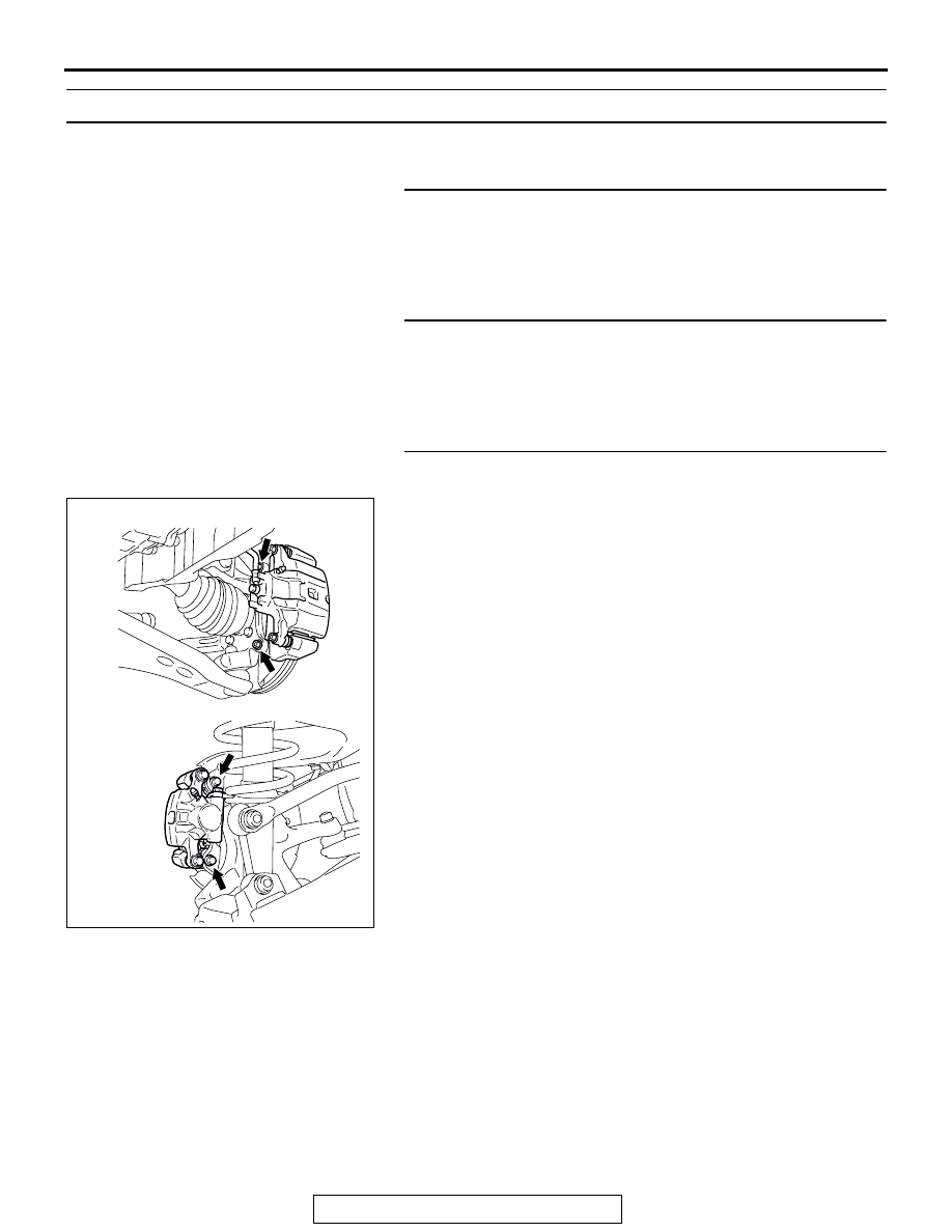
STEP 3. Check for looseness of the caliper installation 
bolt.

Q: Is the caliper installation bolt loose?

YES : Tighten to 100 

± 10 N⋅m (74 ± 7 ft-lb) for the front 

caliper. Tighten to 60 

± 5 N⋅m (45 ± 3 ft-lb) for the rear 

caliper. Then go to Step 5.

NO :  Go to Step 4.

AC308605AB

<FRONT>

<REAR>

SPECIAL TOOLS

TSB Revision

BASIC BRAKE SYSTEM

35A-12

STEP 4. Check the wheel bearings for end play.

(1) Remove the brake discs.
(2) Place a dial gauge as shown, and measure the end play 

while moving the hub in the axial direction.

Limit: 0.05 mm (0.002 inch)

Q: Does the measured end play exceed the limit?

YES : Replace the faulty hub assembly. Then go to Step 5.
NO :  Go to Step 5.

STEP 5. Recheck symptom.
Q: Is the symptom eliminated?

YES : The procedure is complete.
NO :  Start over at step 1. If a new symptom surfaces, refer 

to the symptom chart.

SPECIAL TOOLS

M1351000600360

AC102438 AC

<FRONT>

AC205869AC

<REAR>

TOOL

TOOL NUMBER AND 
NAME

SUPERSESSION

APPLICATION

MB991568
Push rod adjusting socket

General service 
tool

Adjustment of the brake booster 
push rod protrusion amount

MB990964
Brake tool set
A: MB990520
Disc brake piston expander

MB990620-01 or 
general service 
tool

Pushing-in of the disc brake 
piston

MB990964

A

B

ON-VEHICLE SERVICE

TSB Revision

BASIC BRAKE SYSTEM

35A-13

ON-VEHICLE SERVICE

BRAKE PEDAL CHECK AND ADJUSTMENT

M1351000900446

BRAKE PEDAL HEIGHT

1. Turn up the carpet, etc. under the brake pedal.
2. Measure the brake pedal height as illustrated.

Standard value: 169.8 

 172.8 mm (6.69  6.80 inches)

[From the surface of dash panel to the face of pedal 
pad]

3. If the brake pedal height is not within the standard value, 

follow the procedure below.

(1) Disconnect the stoplight switch connector.
(2) Remove the brake booster (Refer to 

P.35A-26

).

NOTE: With the master cylinder and brake pipe con-
nected, remove the brake booster only.

(3) Adjust the brake pedal height by turning the clevis.

NOTE: When the clevis is turned 180 degrees, the pedal 
height is changed by approximately 2.2 mm (0.09 in).

(4) Install the brake booster (Refer to 

P.35A-26

).

(5) Measure the brake pedal height, and ensure that the 

measured value is within the specified value. If it is out of 
the specified value, repeat Step (3) - (6).

(6) Screw in the stop light switch until its thread contacts the 

stopper, and fix the stop light switch by turning it 
approximately one quarter of a turn clockwise. 

(7) Check that the clearance between the stop light switch 

and the stopper is as shown.

CAUTION

Check that the stop light does not illuminate when the 
brake pedal is not depressed.

(8) Connect the connector at the stop light switch.

4. Check the key interlock and shift lock mechanisms. (Refer to 

GROUP 23A, On-vehicle Service 

− Key Interlock and Shift 

Lock Mechanism Chec

P.23A-382

).

5. Return the carpet, etc. to its original position.

AC210522

AC210523 AB

CLEVIS

AC206322 AB

0.5 - 1.5 mm
(0.02 - 0.06 in)

STOPPER

ON-VEHICLE SERVICE

TSB Revision

BASIC BRAKE SYSTEM

35A-14

BRAKE PEDAL FREE PLAY

1. Turn the ignition switch to the "LOCK" (OFF) position, and 

depress the brake pedal two or three times. After eliminating 
the vacuum in the brake booster, press the pedal down by 
hand, and confirm that the amount of movement before 
resistance is met (free play) is within the standard value 
range.

Standard value: 3 

 8 mm (0.12  0.31 inch)

2. If the brake pedal play is not within the standard value, 

check the following, and adjust or replace if necessary:

• Excessive play between the brake pedal and the clevis pin, 

or between the clevis pin and the brake booster operating 
rod

• Brake pedal height

• Installation position of the stop light switch, etc.

CLEARANCE BETWEEN BRAKE PEDAL AND 
DASH PANEL

1. Turn up the carpet, etc. under the brake pedal.
2. Start the engine, depress the brake pedal with 

approximately 500 N (112 pounds) of force, and measure 
the clearance between the brake pedal and the dash panel.

Standard value: 110 mm (4.33 inches) or more [From 
the surface of dash panel to the face of pedal pad]

3. If the clearance is outside the standard value, check for air 

trapped in the brake line and check the thickness of the disc 
brake pad. Andjust and replace defective parts as required.

4. Return the carpet etc. to its original position.

BRAKE BOOSTER OPERATING TEST

M1351001000372

1. For simple checking of the brake booster operation, carry 

out the following tests:

(1) Run the engine for one or two minutes, and then stop it. If 

the pedal depresses fully the first time but gradually 
becomes higher when depressed succeeding times, the 
booster is operating properly. If the pedal height remains 
unchanged, the booster is defective. Go to step 2.

AC206445

AB

AC206446

AB

AC000870

GOOD

NO GOOD

AB


Content   ..  504  505  506  507   ..