Mitsubishi Galant (2004+). Manual - part 509


  Index      Mitsubishi     Mitsubishi Galant - service repair manual 2004 year


Search            


Content   ..  507  508  509  510   ..


Mitsubishi Galant (2004+). Manual - part 509


ON-VEHICLE SERVICE

TSB Revision

BASIC BRAKE SYSTEM

35A-23

CAUTION

• After a new brake disc is installed, always grind the 

brake disc with an on-the-car type brake lathe. If this 
step is not carried out, the brake disc run-out exceeds 
the specified value, resulting in judder.

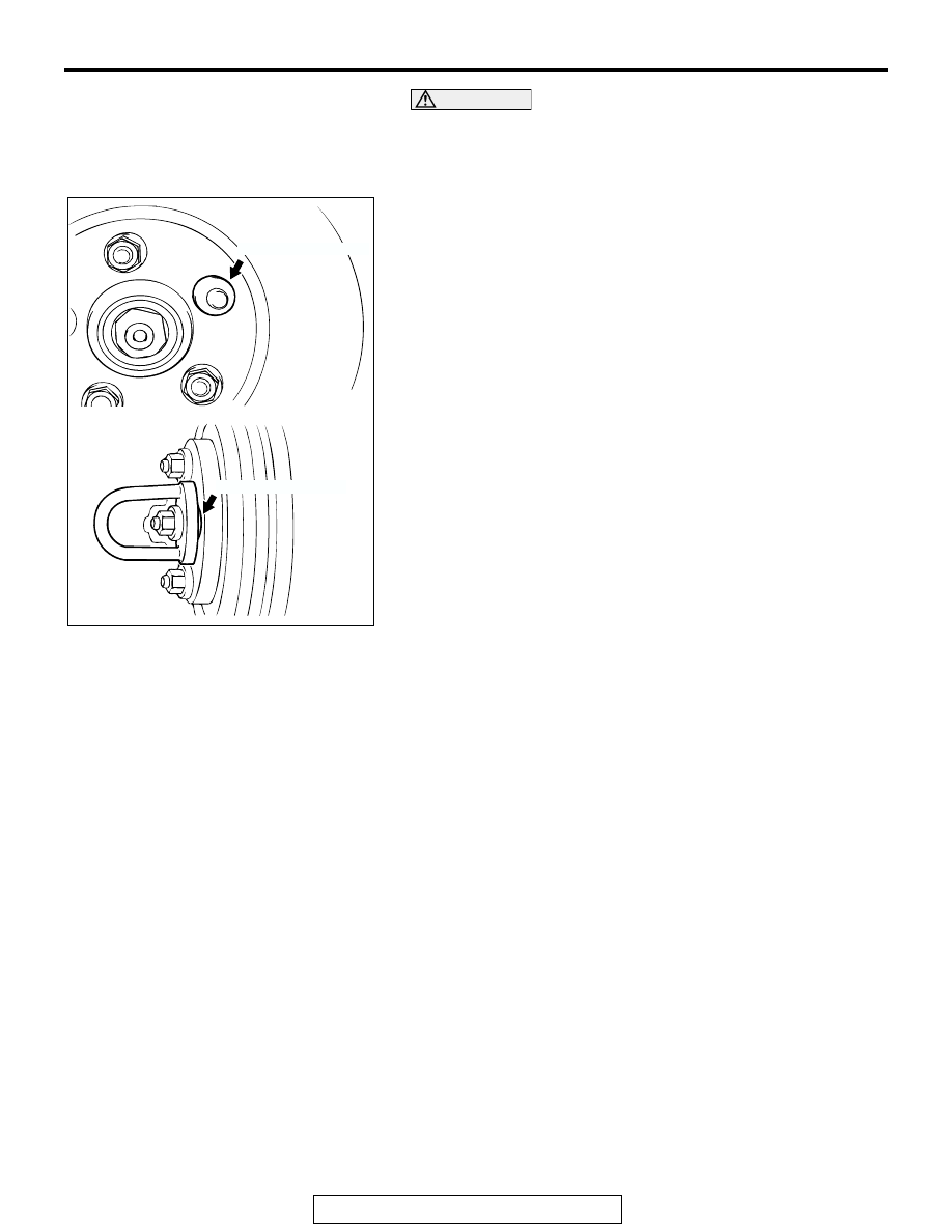
• When the on-the-car type lathe is used, first install a 

M12 flat washer on the stud bolt in the brake disc side 
according to the figure, and then install the adapter. If 
the adapter is installed with M12 flat washer not seated, 
the brake disc rotor may be deformed, resulting in inac-
curate grinding.

• Grind the brake disc with all wheel nuts diagonally and 

equally tightened to the specified torque 100 N

m (74 

ft-lb). If all of the wheel nuts are not used, or the tight-
ening torque is excessive or not equal, the brake disc 
rotor or drum may be deformed, resulting in judder.

5. If the run-out cannot be corrected by changing the phase of 

the brake disc, replace the brake disc or grind it with the 
on-the-car type brake lathe ("MAD, DL-8700PF" or 
equivalent).

MASTER CYLINDER FUNCTION CHECK

M1351010200266

1. Remove the reservoir cap.
2. While watching the open reservoir from a distance of 50 cm 

(20 inches), have an assistant depress the brake pedal. If 
there was a stream of brake fluid rising from the reservoir, 
proceed to Step 3. If there was no stream of brake fluid 
rising from the reservoir, repair or replace the master 
cylinder.

3. While watching the open reservoir from a distance of 50 cm 

(20 inches), have the assistant release the brake pedal. If 
there was a small amount of air bubbles rising through the 
brake fluid, master cylinder function is normal. If there were 
no bubbles rising through the brake fluid, repair or replace 
the master cylinder.

AC006226 AB

M12 FLAT WASHER

M12 FLAT WASHER

BRAKE PEDAL

TSB Revision

BASIC BRAKE SYSTEM

35A-24

BRAKE PEDAL

REMOVAL AND INSTALLATION

M1351003400406

Post-installation Operation
• Brake Pedal Adjustment (Refer to 

P.35A-13

).

AC206452

AB

13 ± 2 N·m
115 ± 18 in-lb

14 ± 2 N·m
122 ± 25 in-lb

10

6

1

2

3

4

9

7

8

5

11

REMOVAL STEPS

1. BRAKE BOOSTER PIN
2. BRAKE BOOSTER PIN ASSEMBLY
3. SHIFT LOCK CABLE CONNECTION
4. STOPLIGHT SWITCH CONNECTOR
5. STOPLIGHT SWITCH
6. BRAKE PEDAL CLIP

WIRING HARNESSES CLAMPED 
ON BRAKE PEDAL ASSEMBLY

7. BRAKE PEDAL BOLT
8. BRAKE BOOSTER NUT
9. BRAKE PEDAL ASSEMBLY
10. BRAKE PEDAL PAD
11. BRAKE PEDAL STOPPER

REMOVAL STEPS (Continued)

BRAKE PEDAL

TSB Revision

BASIC BRAKE SYSTEM

35A-25

INSPECTION

M1351003500221

.

STOPLIGHT SWITCH CHECK
1. Connect an ohmmeter between the stoplight switch 

connector terminals. 

2. There should be no continuity between the terminals when 

the plunger is pushed in as shown. There should be 
continuity when it is released.

TESTER 
CONNECTION

PLUNGER

SPECIFIED 
CONDITION

− 2

IN

Open circuit

OUT

Less than 2

ACX00671AB

NO CONTINUITY CONTINUITY

4 mm

(0.16 in)

MASTER CYLINDER ASSEMBLY AND BRAKE BOOSTER

TSB Revision

BASIC BRAKE SYSTEM

35A-26

MASTER CYLINDER ASSEMBLY AND BRAKE BOOSTER

REMOVAL AND INSTALLATION

M1351003700407

Pre-removal Operation
• Strut Tower Bar Removal (Refer to GROUP 42, Strut 

Tower Bar 

P.42-12

).

• Battery Removal

• Brake Fluid Draining

Post-installation Operation
• Brake Fluid Supplying and Air Bleeding (Refer to 

P.35A-16

).

• Brake Pedal Adjustment (Refer to 

P.35A-13

).

• Battery Installation

• Strut Tower Bar Installation (Refer to GROUP 42, Strut 

Tower Bar 

P.42-12

).

AC306424AB

BRAKE FLUID PROPORTIONING VALVES
<VEHICLES WITHOUT ABS>

3

25 ± 2 N·m
18 ± 2 ft-lb

6

1

2

7

11

15 ± 2 N·m
12 ± 1 ft-lb

2

2

5

9

10

15 ± 2 N·m
12 ± 1 ft-lb

30 ± 5 N·m
22 ± 4 ft-lb

11

BRAKE BOOSTER VACUUM HOSE

4

N

<2.4L ENGINE>

<3.8L ENGINE>

11

14 ± 2 N·m
122 ± 25 in-lb

14

12

13

15

16

8

N

BRAKE MASTER CYLINDER 
ASSEMBLY AND BRAKE FLUID 
PROPORTIONING VALVE 
REMOVAL STEPS

1.

BRAKE FLUID LEVEL INDICATOR 
SWITCH CONNECTOR

2.

BRAKE TUBE CONNECTION

3.

BRAKE FLUID PROPORTIONING 
VALVE <VEHICLES WITHOUT 
ABS>

4.

O-RING

BRAKE MASTER CYLINDER 
ASSEMBLY AND BRAKE FLUID 
PROPORTIONING VALVE 
REMOVAL STEPS (Continued)


Content   ..  507  508  509  510   ..