Mitsubishi Galant (2004+). Manual - part 495


  Index      Mitsubishi     Mitsubishi Galant - service repair manual 2004 year


Search            


Content   ..  493  494  495  496   ..


Mitsubishi Galant (2004+). Manual - part 495


DIAGNOSIS

TSB Revision

CONTROLLER AREA NETWORK (CAN)

54C-591

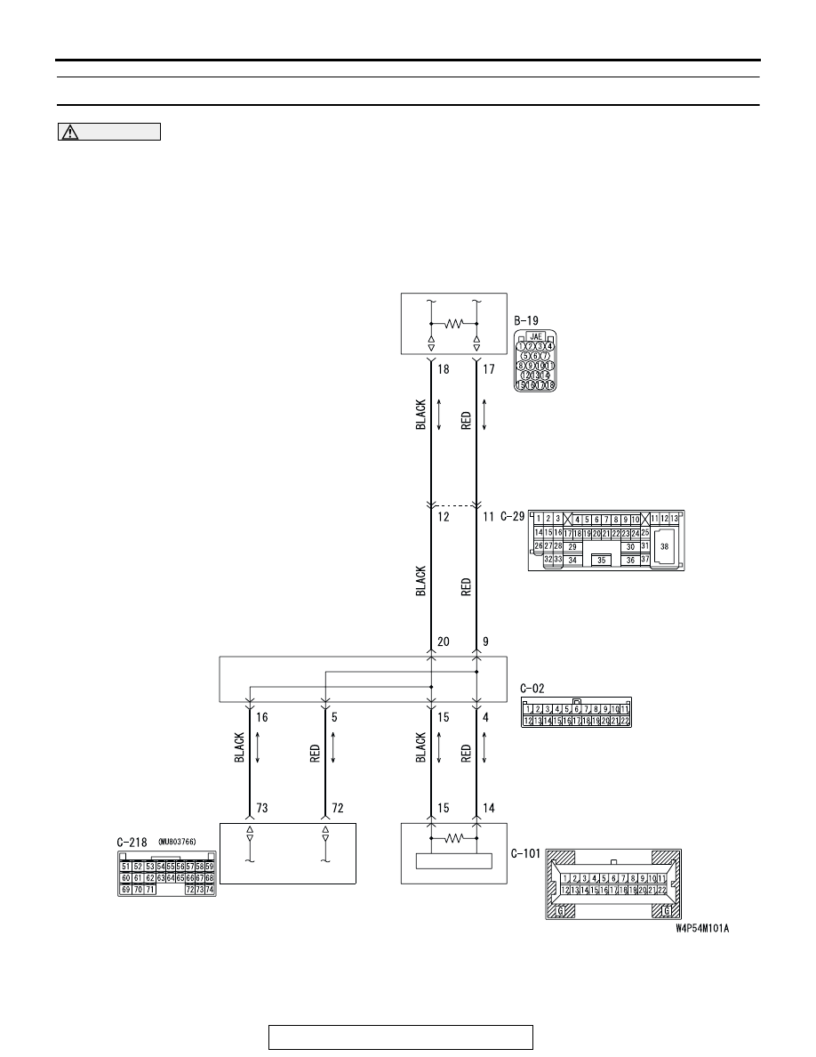
DIAGNOSTIC ITEM 20: Failure in the lines between CAN main bus line and the ETACS-ECU.

CAUTION

When servicing a CAN bus line, ground yourself 
by touching a metal object such as an unpainted 
water pipe. If you fail to do so, a component con-
nected to the CAN bus line may be damaged.

POWERTRAIN
CONTROL MODULE

JOINT
CONNECTOR (3)

ETACS-ECU

COMBINATION
METER

<WITHOUT ELECTRONIC BRAKE-FORCE DISTRIBUTION (EBD)
  AND ANTI-LOCK BRAKING SYSTEM (ABS)>

DIAGNOSIS

TSB Revision

CONTROLLER AREA NETWORK (CAN)

54C-592

.

POWERTRAIN
CONTROL 
MODULE

JOINT
CONNECTOR (3)

ETACS-ECU

COMBINATION
METER

<WITH ELECTRONIC BRAKE-FORCE DISTRIBUTION (EBD)
  AND ANTI-LOCK BRAKING SYSTEM (ABS)>

ABS-ECU

AC305231BD

CONNECTOR: C-02

AC305413

C-218 (GR)

CONNECTOR: C-218

AJ

JUNCTION BLOCK
(REAR VIEW)

DIAGNOSIS

TSB Revision

CONTROLLER AREA NETWORK (CAN)

54C-593

TROUBLE JUDGMENT
If the MUT-III cannot received signals from 
ETACS-ECU, CAN bus line connector(s) are broken 
or an open circuit has occurred.

.

COMMENTS ON TROUBLE SYMPTOM
The wiring harness wire or connectors may have 
loose, corroded, or damage terminals, or terminals 
pushed back in the connector, or the ETACS-ECU 
may be defective.

.

TROUBLESHOOTING HINTS

• The wiring harness or connectors may have 

loose, corroded, or damage terminals, or termi-
nals pushed back in the connector

• The ETACS-ECU may be defective

DIAGNOSIS

Required Special Tool:

• MB991223: Harness Set

STEP 1. Check joint connector (3) C-02 and ETACS-ECU 
connector C-218 for loose, corroded or damaged 
terminals, or terminals pushed back in the connector.

CAUTION

The strand end of the twisted wire should be within 10 cm 
(4 inches) from the connector. For details refer to 

P.54C-4

.

Check the joint connector at the wiring harness side for loose, 
corroded or damaged terminals, or terminals pushed back in 
the connector, and also check the short pin behind the connec-
tor for corrosion, deformation and delamination.
Q: Are joint connector (3) C-02 and ETACS-ECU connector 

C-218 in good condition?
YES : 
Go to Step 2.
NO :  Repair the damaged parts. Replace the joint 

connector as necessary.

AC305231AP

CONNECTOR: C-02

AC305413

C-218 (GR)

CONNECTOR: C-218

AI

HARNESS SIDE

JUNCTION BLOCK
(REAR VIEW)

68

74

63

66

72

73

67

65 64

61

70

71

62

69

60

57

58

59

56 55

52

54 53

51

AC209350

1

12

2

13

3

14

4

15

5

16

6

17

7

18

8

19

9

20

10

21

11

22

AB

SHORT PIN

DIAGNOSIS

TSB Revision

CONTROLLER AREA NETWORK (CAN)

54C-594

STEP 2. Check the CAN bus lines between joint connector 
(3) and the ETACS-ECU. Measure the resistance between 

joint connector (3) C-02 and ETACS-ECU connector C-218.

CAUTION

A digital multimeter should be used. For details refer to 

P.54C-4

.

CAUTION

The test wiring harness should be used. For details refer to 

P.54C-4

.

(1) Disconnect joint connector (3) C-02 and ETACS-ECU 

connector C-218, and measure the resistances at the wiring 
harness sides of joint connector (3) C-02 and ETACS-ECU 
connector C-218.

(2) Turn the ignition switch to the "LOCK" (OFF) position.

CAUTION

Disconnect the negative battery terminal. For details refer 
to 

P.54C-4

.

(3) Disconnect the negative battery terminal.

AC305231AP

CONNECTOR: C-02

AC305413

C-218 (GR)

CONNECTOR: C-218

AI

HARNESS SIDE

JUNCTION BLOCK
(REAR VIEW)

68

74

63

66

72

73

67

65 64

61

70

71

62

69

60

57

58

59

56 55

52

54 53

51


Content   ..  493  494  495  496   ..