Mitsubishi Galant (2004+). Manual - part 453


  Index      Mitsubishi     Mitsubishi Galant - service repair manual 2004 year


Search            


Content   ..  451  452  453  454   ..


Mitsubishi Galant (2004+). Manual - part 453


DIAGNOSIS

TSB Revision

CONTROLLER AREA NETWORK (CAN)

54C-423

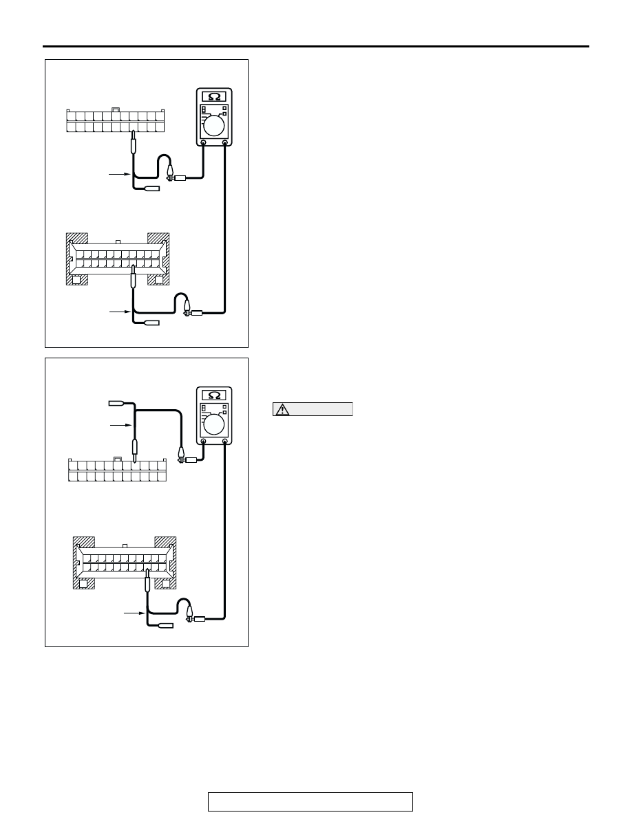
(4) Measure the resistance between joint connector (3) 

terminal 15 and combination meter connector terminal 15.

OK: 2 ohms or less

(5) Measure the resistance between joint connector (3) 

terminal 4 and combination meter connector terminal 14.

OK: 2 ohms or less

CAUTION

Strictly observe the specified wiring harness repair proce-
dure. For details refer to 

P.54C-5

.

Q: Do all the resistances measure 2 ohms or less?

YES : If all the resistances measure 2 ohms or less, go to 

Step 6.

NO :  If either of the resistances measures more than 2 

ohms or all the resistances measure more than 2 
ohms, repair the wiring harness between joint 
connector (3) and the combination meter connector, 
and then go to Step 2.

AC204582

11

22

10

21

9

20

8

19

7

18

6

17

5

16

4

15

3

14

2

13

1

12

AC204582DB

HARNESS SIDE: C-02

TEST 
HARNESS

G

G

22

11

5

16

19

20

21

17

18

8

10 9

7 6

13

1514

12

2

4 3

1

TEST 
HARNESS

HARNESS SIDE: C-101

AC204582

HARNESS SIDE: C-02

TEST 
HARNESS

DC

11

22

10

21

9

20

8

19

7

18

6

17

5

16

4

15

3

14

2

13

1

12

G

G

22

11

5

16

19

20

21

17

18

8

10 9

7 6

13

1514

12

2

4 3

1

TEST 
HARNESS

HARNESS SIDE: C-101

DIAGNOSIS

TSB Revision

CONTROLLER AREA NETWORK (CAN)

54C-424

STEP 6. Check the terminator resistor inside the 
combination meter. Measure the resistance at combination 

meter connector C-101.

CAUTION

A digital multimeter should be used. For details refer to 

P.54C-4

.

(1) Disconnect combination meter C-101, and measure the 

resistance at the component side of combination meter 
connector C-101.

(2) Measure the resistance between combination meter 

connector terminals 14 and 15.

OK: 120 

± 20 

Q: Does the resistance measure 120 

± 20 ?

YES : If the resistance measures 120 

± 20 Ω, go to Step 2.

NO :  If the resistance does not measure 120 

± 20 Ω, 

replace the combination meter, and then go to Step 2.

AC305231AQ

CONNECTOR: C-101

HARNESS SIDE

AC204582BY

COMPONENT SIDE: C-101

G

11

22

17

3

14

G

12

1

13

2

15

4

16

5

18

7

6

19

8

10

21

20

9

TEST 
HARNESS

TEST HARNESS

DIAGNOSIS

TSB Revision

CONTROLLER AREA NETWORK (CAN)

54C-425

STEP 7. Check the CAN bus lines (communication line 
only) between intermediate connector C-29 and joint 
connector (3). Measure the resistance at intermediate 

connector C-29 and joint connector (3) C-02.

CAUTION

A digital multimeter should be used. For details refer to 

P.54C-4

.

CAUTION

The test wiring harness should be used. For details refer to 

P.54C-4

.

(1) Disconnect joint connector (3) C-02 and intermediate 

connector C-29, and measure the resistance between the 
wiring harness side connector of joint connector (3) C-02 
and the female side connector of intermediate connector 
C-29 (instrument panel wiring harness side).

(2) Turn the ignition switch to the "LOCK" (OFF) position.

CAUTION

Disconnect the negative battery terminal. For details refer 
to 

P.54C-4

.

(3) Disconnect the negative battery terminal.

AC305232

CONNECTORS: C-02, C-29

AG

C-02

C-02

C-29

C-29

DIAGNOSIS

TSB Revision

CONTROLLER AREA NETWORK (CAN)

54C-426

(4) Measure the resistance between intermediate connector 

terminal 12 and joint connector (3) terminal 20.

OK: 2 ohms or less

(5) Measure the resistance between intermediate connector 

terminal 11 and joint connector (3) terminal 9.

OK: 2 ohms or less

CAUTION

Strictly observe the specified wiring harness repair proce-
dure. For details refer to 

P.54C-5

.

Q: Do all the resistances measure 2 ohms or less?

YES : If all the resistances measure 2 ohms or less, go to 

Step 2.

NO :  If either of the resistances measures more than 2 

ohms or all the resistances measure more than 2 
ohms, repair the wiring harness between joint 
connector (3) and the intermediate connector, and 
then go to Step 2. 

AC204582

35

34

36

30

38

29

17

13 12 11

37

31

33 32

26

27

28

16

14

15

3 2

4

18

6

7

21 20

5

19

9

10

24 23

25

8

22

1

TEST 
HARNESS

FEMALE SIDE: C-29

HARNESS SIDE: C-02

TEST 
HARNESS

11

22

10

21

9

20

8

19

7

18

6

17

5

16

4

15

3

14

2

13

1

12

DF

AC204582

35

34

36

30

38

29

17

13 12 11

37

31

33 32

26

27

28

16

14

15

3 2

4

18

6

7

21 20

5

19

9

10

24 23

25

8

22

1

TEST 
HARNESS

FEMALE SIDE: C-29

HARNESS SIDE: C-02

TEST HARNESS

11

22

10

21

9

20

8

19

7

18

6

17

5

16

4

15

3

14

2

13

1

12

DE


Content   ..  451  452  453  454   ..