Mitsubishi Galant (2004+). Manual - part 451


  Index      Mitsubishi     Mitsubishi Galant - service repair manual 2004 year


Search            


Content   ..  449  450  451  452   ..


Mitsubishi Galant (2004+). Manual - part 451


DIAGNOSIS

TSB Revision

CONTROLLER AREA NETWORK (CAN)

54C-415

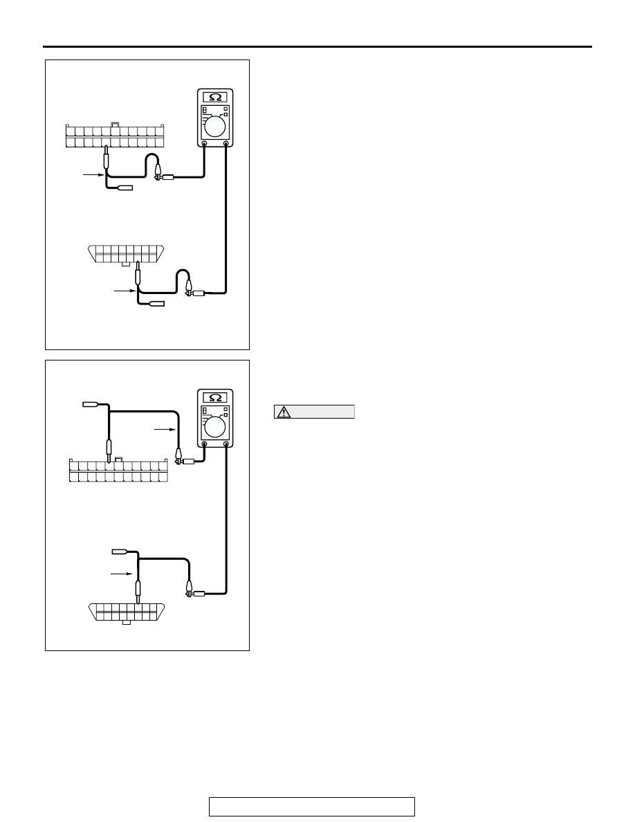
(4) Measure the resistance between joint connector (3) 

terminal 18 and data link connector terminal 14.

OK: 2 ohms or less

(5) Measure the resistance between joint connector (3) 

terminal 7 and data link connector terminal 6.

OK: 2 ohms or less

CAUTION

Strictly observe the specified wiring harness repair proce-
dure. For details refer to 

P.54C-5

.

Q: Do all the resistances measure 2 ohms or less?

YES <all the resistances measure 2 ohms or less: When 
any repair done> : 
Retest the system.
YES <all the resistances measure 2 ohms or less: When 
no repair done> : 
Diagnose CAN bus lines thoroughly by 

referring to 

P.54C-571

 <Vehicles without multi-center 

display (middle-grade type)> or 

P.54C-584

 <Vehicles 

with multi-center display (middle-grade type)>.

AC204582DI

11

22

10

21

9

20

8

19

7

18

6

17

5

16

4

15

3

14

2

13

1

12

TEST 
HARNESS

HARNESS SIDE: C-02

TEST 
HARNESS

Y

8

16

15

7

5

1314

6

12

4

2

1011

3

9

1

HARNESS SIDE: C-125

AC204582

HARNESS SIDE: C-02

TEST 
HARNESS

DH

11

22

10

21

9

20

8

19

7

18

6

17

5

16

4

15

3

14

2

13

1

12

Y

8

16

15

7

5

1314

6

12

4

2

1011

3

9

1

TEST 
HARNESS

HARNESS SIDE: C-125

DIAGNOSIS

TSB Revision

CONTROLLER AREA NETWORK (CAN)

54C-416

DIAGNOSTIC ITEM 11: Diagnose terminator resistors at both ends <Vehicles with ABS>

CAUTION

When servicing a CAN bus line, ground yourself 
by touching a metal object such as an unpainted 
water pipe. If you fail to do so, a component con-
nected to the CAN bus line may be damaged.

POWERTRAIN
CONTROL MODULE

ABS-ECU

JOINT
CONNECTOR (3)

COMBINATION
METER

DIAGNOSIS

TSB Revision

CONTROLLER AREA NETWORK (CAN)

54C-417

.

TROUBLE JUDGMENT
The terminator resistors at both ends of CAN bus 
lines may be damaged, when the resistance 
between the CAN bus lines (CAN_L and H lines) is 
more than 2 ohms.

.

COMMENTS ON TROUBLE SYMPTOM
The CAN bus line harness wires or connectors may 
be damaged (open circuit may be present on CAN_L 
or CAN_H line between the data link connector and 
CAN main bus lines, or CAN main bus lines may be 
open at both sides), or the combination meter and 
the powertrain control module may be defective.

.

TROUBLESHOOTING HINTS

• The wiring harness or connectors may have 

loose, corroded, or damage terminals, or termi-
nals pushed back in the connector

• The combination meter may be defective

• The ABS-ECU may be defective

• The powertrain control module may be defective

DIAGNOSIS

Required Special Tools:

• MB991223: Harness Set

• MB991970: ABS Check Harness

AC305206

CONNECTOR: A-02

AR

A-02 (GR)

AC306248AB

B-19 (B)

CONNECTOR: B-19

AIR
CLEANER

PCM

AC305231CA

C-101

C-29

C-02

CONNECTORS: C-02, C-29, C-101

DIAGNOSIS

TSB Revision

CONTROLLER AREA NETWORK (CAN)

54C-418

STEP 1. Check intermediate connector C-29 for loose, 
corroded or damaged terminals, or terminals pushed back 
in the connector.

CAUTION

The strand end of the twisted wire should be within 10 cm 
(4 inches) from the connector. For details refer to 

P.54C-4

.

Q: Is intermediate connector C-29 in good condition?

YES : Go to Step 2.
NO :  Repair the damaged parts.

AC305231AI

CONNECTOR: C-29


Content   ..  449  450  451  452   ..