Mitsubishi Galant (2004+). Manual - part 409
DIAGNOSIS
TSB Revision
CONTROLLER AREA NETWORK (CAN)
54C-247
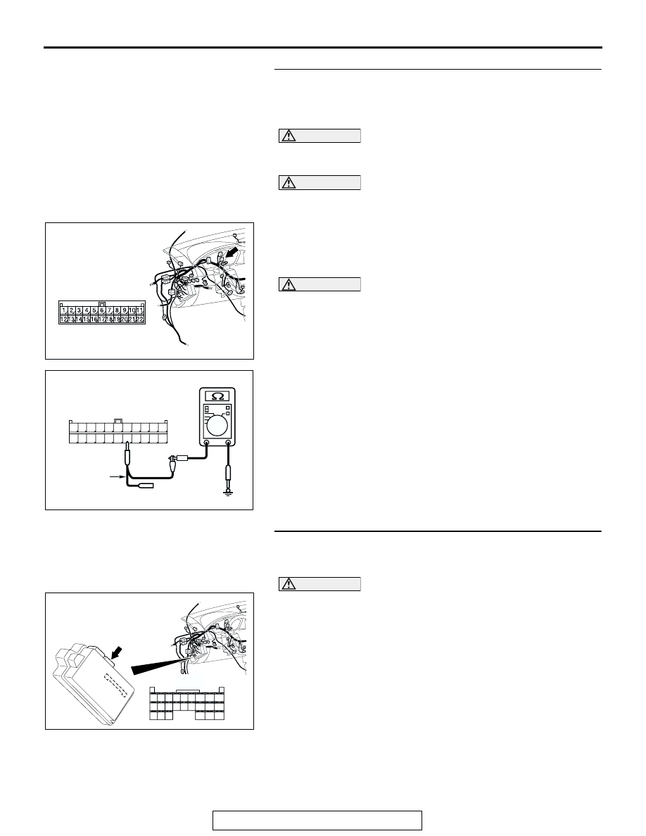
STEP 32. Check the CAN_L line (communication line
including the ETACS-ECU) between joint connector (3) and
the ETACS-ECU connector for short to ground. Measure
the resistance at joint connector (3) C-02.
CAUTION
A digital multimeter should be used. For details refer to
CAUTION
The test wiring harness should be used. For details refer to
(1) Disconnect joint connector (3) C-02, and measure the
resistance at the wiring harness side of joint connector (3)
C-02.
(2) Turn the ignition switch to the "LOCK" (OFF) position.
CAUTION
Disconnect the negative battery terminal. For details refer
to
.
(3) Disconnect the negative battery terminal.
(4) Measure the resistance between joint connector (3)
terminal 16 and body ground.
OK: 1 k
Ω or more
Q: Does the resistance measure 1 k
Ω or more?
YES : If the resistance measures 1 k
Ω or more, go to Step
35 .
NO : If the resistance measures less than 1 k
Ω, go to Step
33.
STEP 33. Check ETACS-ECU connector C-218 for loose,
corroded or damaged terminals, or terminals pushed back
in the connector.
CAUTION
The strand end of the twisted wire should be within 10 cm
(4 inches) from the connector. For details refer to
Q: Is ETACS-ECU connector C-218 in good condition?
YES : Go to Step 34.
NO : Repair the damaged parts.
AC305231AP
CONNECTOR: C-02
AC209364II
11
22
10
21
9
20
8
19
7
18
6
17
5
16
4
15
3
14
2
13
1
12
HARNESS SIDE: C-02
TEST
HARNESS
AC305413
C-218 (GR)
CONNECTOR: C-218
AI
HARNESS SIDE
JUNCTION BLOCK
(REAR VIEW)
68
74
63
66
72
73
67
65 64
61
70
71
62
69
60
57
58
59
56 55
52
54 53
51