Mitsubishi Galant (2004+). Manual - part 272


  Index      Mitsubishi     Mitsubishi Galant - service repair manual 2004 year


Search            


Content   ..  270  271  272  273   ..


Mitsubishi Galant (2004+). Manual - part 272


SYMPTOM PROCEDURES

TSB Revision

SIMPLIFIED WIRING SYSTEM (SWS)

54B-279

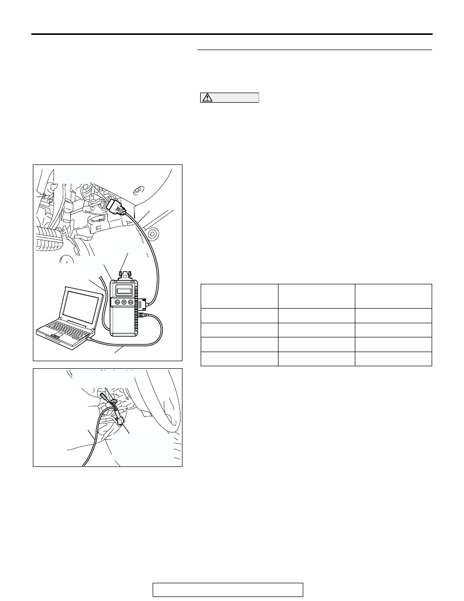
STEP 1. Check the input signal by using "DATA LIST" 
menu of the SWS monitor.

Turn the ignition switch to the ACC position before checking 
input signals from the windshield wiper switch.

CAUTION

To prevent damage to scan tool MB991958, always turn the 
ignition switch to the "LOCK" (OFF) position before con-
necting or disconnecting scan tool MB991958. Connect 
special tool MB991910 before connecting special tool 
MB991812. Be sure to connect special tool MB991806 after 
turning on special tool MB991824.
(1) Connect the special tool. Refer to "How to connect SWS 

monitor 

P.54B-13

."

(2) Operate scan tool MB991958 according to the procedure 

below to display "COLUMN ECU."
a. Select "Interactive Diagnosis."
b. Select "System select."
c. Select "SWS."
d. Select "SWS MONITOR."
e. Select "Data List."
f. Select "COLUMN ECU."

(3) Check that normal conditions are displayed for the items 

described in the table below.

Q: Are normal conditions displayed for "INT WIPER SW", 

"LO WIPER SW", "HI WIPER SW" and "MIST WIPER 
SW"?
YES : 
Go to Step 2.
NO :  Refer to Inspection Procedure M-6 "ETACS-ECU 

does not receive any signal from the windshield mist 
switch 

P.54B-509

."

ITEM NO.

ITEM NAME

NORMAL 
CONDITION

ITEM 05

INT WIPER SW

ON

ITEM 06

LO WIPER SW

ON

ITEM 07

HI WIPER SW

ON

ITEM 08

MIST WIPER SW

ON

AC305411AB

MB991910

DATA LINK

CONNECTOR

MB991827

MB991824

MB991806

MB991812

AC302210

COLUMN SWITCH 
CONNECTOR

COLUMN SWITCH 
CONNECTOR AT 
HARNESS SIDE 

MB991812

AB

SYMPTOM PROCEDURES

TSB Revision

SIMPLIFIED WIRING SYSTEM (SWS)

54B-280

STEP 2. Check windshield wiper motor connector A-03 for 
loose, corroded or damaged terminals, or terminals 
pushed back in the connector.

Q: Is windshield wiper motor connector A-03 in good 

condition?
YES : 
Go to Step 3.
NO :  Repair or replace the damaged component(s). Refer 

to GROUP 00E, Harness Connector Inspection 

P.00E-2

. Verify that the windshield wiper operates 

normally when the windshield wiper switch is moved 
to each position.

STEP 3. Check the windshield wiper motor.

(1) Disconnect windshield wiper motor connector A-03.

(2) Connect a battery to the windshield wiper motor as shown. 

Then check the windshield wiper motor operates normally 

at high and low speeds.

Q: Does the windshield wiper motor operate normally?

YES : Go to Step 4.
NO :  Replace the windshield wiper motor. Verify that the 

windshield wiper operates normally when the 
windshield wiper switch is moved to each position.

AC305206

A-03 (B)

HARNESS SIDE

CONNECTOR: A-03

AH

AC305206

A-03 (B)

HARNESS SIDE

CONNECTOR: A-03

AH

AC306750

1

2

3

4

5

1

2

3

4

5

1

2

3

4

5

CHECK OPERATION

LOW SPEED

HIGH SPEED

AB

SYMPTOM PROCEDURES

TSB Revision

SIMPLIFIED WIRING SYSTEM (SWS)

54B-281

STEP 4. Check front-ECU connector A-12X for loose, 
corroded or damaged terminals, or terminals pushed back 
in the connector.

Q: Is front-ECU connector A-12X in good condition?

YES : Go to Step 5.
NO :  Repair or replace the damaged component(s). Refer 

to GROUP 00E, Harness Connector Inspection 

P.00E-2

. Verify that the windshield wiper operates 

normally when the windshield wiper switch is moved 
to each position.

STEP 5. Check the wiring harness between windshield 
wiper motor connector A-03 (terminals 1 and 2) and 
front-ECU connector A-12X (terminals 25 and 24).

Q: Is the wiring harness between windshield wiper motor 

connector A-03 (terminals 1 and 2) and front-ECU 
connector A-12X (terminals 25 and 24) in good 
condition?
YES : 
No action is necessary and testing is complete.
NO :  The wiring harness may be damaged or the 

connector(s) may have loose, corroded or damaged 
terminals, or terminals pushed back in the connector. 
Repair the wiring harness as necessary. Verify that 
the windshield wiper operates normally when the 
windshield wiper switch is moved to each position.

AC305977

CONNCTOR: A-12X

AI

21

22

23

24

25

26

27

28

29

30

31

RELAY BOX SIDE

AC305206

A-03 (B)

HARNESS SIDE

CONNECTOR: A-03

AH

AC305977

CONNCTOR: A-12X

AI

21

22

23

24

25

26

27

28

29

30

31

RELAY BOX SIDE

SYMPTOM PROCEDURES

TSB Revision

SIMPLIFIED WIRING SYSTEM (SWS)

54B-282

INSPECTION PROCEDURE G-4: Windshield Wiper and Washer: Windshield wipers does not stop at 
the predetermined park position.

.

WINDSHIELD
WIPER MOTOR

FRONT-ECU

WIPER 
AUTOMATIC 
STOP RELAY

RELAY
BOX

IGNITION
SWITCH (ACC)

Windshield Wiper Automatic Stop Relay Circuit

AC305206

A-03 (B)

CONNECTOR: A-03

AI

AC305977

CONNECTOR: A-12X

AF

AC305231

CONNECTOR: C-29

AH


Content   ..  270  271  272  273   ..