Mitsubishi Galant (2004+). Manual - part 224


  Index      Mitsubishi     Mitsubishi Galant - service repair manual 2004 year


Search            


Content   ..  222  223  224  225   ..


Mitsubishi Galant (2004+). Manual - part 224


SYMPTOM PROCEDURES

TSB Revision

SIMPLIFIED WIRING SYSTEM (SWS)

54B-87

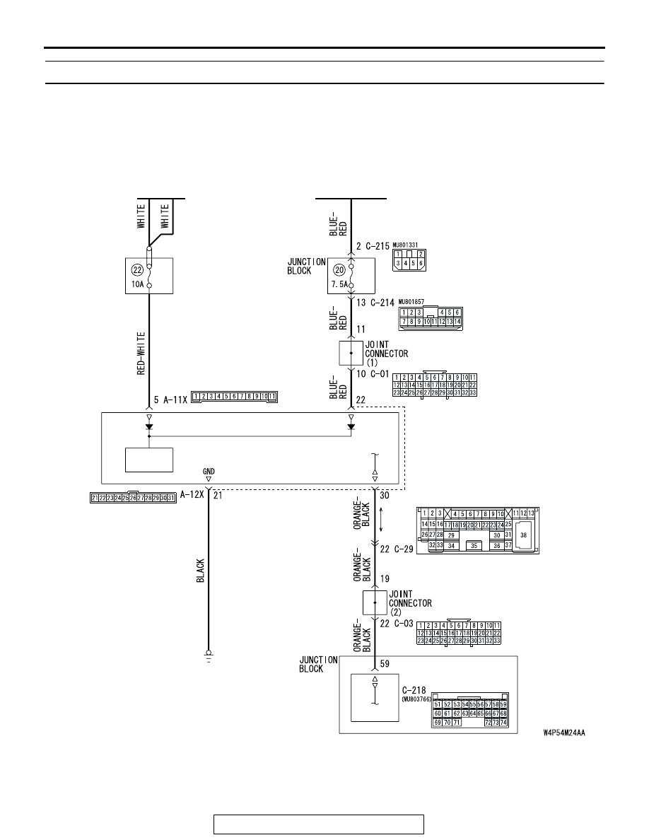
INSPECTION PROCEDURE A-4: Communication with the Front-ECU is not Possible.

NOTE: This troubleshooting procedure requires the 
use of scan tool MB991958 and SWS monitor kit 
MB991813. For details on how to use the SWS mon-
itor, refer to "How to use SWS monitor 

P.54B-15

."

RELAY 
BOX

BATTERY

IGNITION
SWITCH (IG2)

POWER
SOURCE

ETACS-ECU

FRONT-
ECU

Front-ECU Power Supply and SWS Communication Circuit

SYMPTOM PROCEDURES

TSB Revision

SIMPLIFIED WIRING SYSTEM (SWS)

54B-88

.

CIRCUIT OPERATION

• The power supply to the front-ECU is provided by 

the battery and the ignition switch (IG2).

• If the power supply system from the battery is 

defective, the system operates by the power sup-
ply from the ignition switch (IG2).

.

TECHNICAL DESCRIPTION (COMMENT)
It is suspected that the power supply circuit to the 
front-ECU is defective, or the wiring harness 
between the SWS monitor kit and the front-ECU or 
their connector(s) is damaged. If the battery power 
supply circuit to the ECU (terminal 5 of the 
front-ECU) is damaged, also check the power supply 
circuit from the ignition switch (IG2) (terminal 22 of 
the front-ECU), and repair if necessary.

.

TROUBLESHOOTING HINTS

• The wiring harness or connectors may have 

loose, corroded, or damaged terminals, or termi-
nals pushed back in the connector

• The front-ECU may be defective

• The ETACS-ECU may be defective

DIAGNOSIS

Required Special Tools:

• MB991223: Harness Set

• MB991958: Scan Tool (MUT-III Sub Assembly)

• MB991824: Vehicle Communication Interface (V.C.I.)

• MB991827: MUT-III USB Cable

• MB991910: MUT-III Main Harness A

• MB991813: SWS Monitor Kit

• MB991806: SWS Monitor Cartridge

• MB991812: SWS Monitor Harness (For Column-ECU)

• MB991822: Probe Harness

AC305977AG

CONNECTORS: A-11X, A-12X

A-12X

A-11X

AC305231

C-29

C-03

CONNECTORS: C-03, C-29

BK

AC305413AL

CONNECTOR: C-218

C-218 (GR)

SYMPTOM PROCEDURES

TSB Revision

SIMPLIFIED WIRING SYSTEM (SWS)

54B-89

STEP 1. Use scan tool MB991958 to select "ECU COMM 
Check" on the SWS monitor display.

Check the ETACS-ECU.

CAUTION

To prevent damage to scan tool MB991958, always turn the 
ignition switch to the "LOCK" (OFF) position before con-
necting or disconnecting scan tool MB991958. Connect 
special tool MB991910 before connecting special tool 
MB991812. Be sure to connect special tool MB991806 after 
turning on special tool MB991824.
(1) Connect the special tool. Refer to "How to connect SWS 

monitor 

P.54B-13

."

(2) Turn the ignition switch to the "LOCK" (OFF) position.
(3) Operate scan tool MB991958 according to the procedure 

below to display "ECU COMM Check."
a. Select "Interactive Diagnosis."
b. Select "System select."
c. Select "SWS."
d. Select "SWS MONITOR."
e. Select "ECU COMM Check."

(4) Scan tool MB991958 should show "OK" on the "ECU 

COMM Check" menu for the "ETACS ECU" menu.

Q: Is "OK" displayed for the "ETACS ECU" menu?

YES : Go to Step 2.
NO :  Refer to Inspection Procedure A-3 "Communication 

with the ETACS-ECU is not possible 

P.54B-79

."

AC305411AB

MB991910

DATA LINK

CONNECTOR

MB991827

MB991824

MB991806

MB991812

AC302210

COLUMN SWITCH 
CONNECTOR

COLUMN SWITCH 
CONNECTOR AT 
HARNESS SIDE 

MB991812

AB

SYMPTOM PROCEDURES

TSB Revision

SIMPLIFIED WIRING SYSTEM (SWS)

54B-90

STEP 2. Check front-ECU connector A-11X for loose, 
corroded or damaged terminals, or terminals pushed back 
in the connector.

Q: Is front-ECU connector A-11X in good condition?

YES : Go to Step 3.
NO :  Repair or replace the damaged component(s). Refer 

to GROUP 00E, Harness Connector Inspection 

P.00E-2

. The system should communicate with the 

front-ECU normally.

STEP 3. Check the battery power supply circuit to the 
front-ECU. Measure the voltage at front-ECU connector 
A-11X.

(1) Disconnect front-ECU connector A-11X and measure the 

voltage available at the relay box side of the connector.

(2) Measure the voltage between terminal 5 and ground.

• The voltage should measure approximately 12 volts 

(battery positive voltage).

Q: Is the measured voltage approximately 12 volts (battery 

positive voltage)?
YES : 
Go to Step 5.
NO :  Go to Step 4.

AC305977AH

CONNECTOR: A-11X

RELAY BOX SIDE 

AC305977AH

CONNECTOR: A-11X

RELAY BOX SIDE 

5

11

9

10

8 7 6

2

4 3

1

AC209865AB

CONNECTOR A-11X
(RELAY BOX SIDE)


Content   ..  222  223  224  225   ..