Mitsubishi Galant (2004+). Manual - part 222


  Index      Mitsubishi     Mitsubishi Galant - service repair manual 2004 year


Search            


Content   ..  220  221  222  223   ..


Mitsubishi Galant (2004+). Manual - part 222


SYMPTOM PROCEDURES

TSB Revision

SIMPLIFIED WIRING SYSTEM (SWS)

54B-79

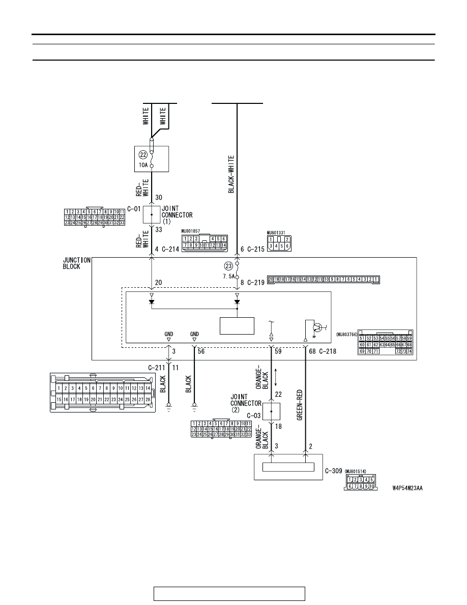
INSPECTION PROCEDURE A-3: Communication with the ETACS-ECU is not Possible.

RELAY 
BOX

BATTERY

IGNITION
SWITCH (IG1)

COLUMN 
SWITCH

COLUMN -ECU

ETACS-
ECU

POWER
SOURCE

JUNCTION BLOCK SIDE

ETACS-ECU Power Supply and SWS Communication Circuit

SYMPTOM PROCEDURES

TSB Revision

SIMPLIFIED WIRING SYSTEM (SWS)

54B-80

.

CIRCUIT OPERATION

• The power supply to the ETACS-ECU is provided 

by the battery and the ignition switch (IG1).

• If the power supply system from the battery is 

defective, the system operates by the power sup-
ply from the ignition switch (IG1).

.

TECHNICAL DESCRIPTION (COMMENT)
It is suspected that the power supply circuit to the 
ETACS-ECU is defective, or the wiring harness 
between the SWS monitor kit and the ETACS-ECU 
or their connector(s) is damaged. If the battery power 
supply circuit to the ECU (terminal 20 of the 

ETACS-ECU) is damaged, also check the power 
supply circuit from the ignition switch (IG1) (terminal 
8 of the ETACS-ECU), and repair if necessary. If the 
ground circuit to the ECU (terminal 3 of the 
ETACS-ECU) is damaged, also check the ground cir-
cuit to the sensor (terminal 56 of the ETACS-ECU), 
and repair if necessary.

.

TROUBLESHOOTING HINTS

• The wiring harness or connectors may have 

loose, corroded, or damaged terminals, or termi-
nals pushed back in the connector

• The ETACS-ECU may be defective

DIAGNOSIS

Required Special Tools:

• MB991223: Harness Set

• MB991958: Scan Tool (MUT-III Sub Assembly)

• MB991824: Vehicle Communication Interface (V.C.I.)

• MB991827: MUT-III USB Cable

• MB991910: MUT-III Main Harness A

AC305231BC

CONNECTORS: C-01, C-03

C-01

C-03

AC305415

CONNECTORS: C-204, C-214

AQ

C-204

C-214

AC305413

C-219

C-218 (GR)

CONNECTORS: C-218, C-219

AM

AC305235AC

CONNECTOR: C-309

SYMPTOM PROCEDURES

TSB Revision

SIMPLIFIED WIRING SYSTEM (SWS)

54B-81

STEP 1. Check ETACS-ECU connectors C-218 and C-219 
for loose, corroded or damaged terminals, or terminals 
pushed back in the connector.

Q: Are ETACS-ECU connectors C-218 and C-219 in good 

condition?
YES : 
Go to Step 2.
NO :  Repair or replace the damaged component(s). Refer 

to GROUP 00E, Harness Connector Inspection 

P.00E-2

. The system should communicate with the 

ETACS-ECU normally.

STEP 2. Check the battery power supply circuit to the 
ETACS-ECU. Measure the voltage at ETACS-ECU 
connector C-219.

(1) Disconnect ETACS-ECU connector C-219 and measure the 

voltage available at the junction block side of the connector.

(2) Measure the voltage between terminal 20 and ground.

• The voltage should measure approximately 12 volts 

(battery positive voltage).

Q: Is the measured voltage approximately 12 volts (battery 

positive voltage)?
YES : 
Go to Step 4.
NO :  Go to Step 3.

AC305414

CONNECTORS: C-218, C-219

JUNCTION BLOCK
(REAR VIEW)

C-219

C-218 (GR)

HARNESS SIDE

C-218

C-219

51

52

53

54

55

56

57

58

59

60

61

62

63

64

65

66

67

68

69

70

71

72

73

74

JUNCTION BLOCK SIDE

AC

AC305413 AG

CONNECTOR: C-219

JUNCTION BLOCK SIDE

JUNCTION BLOCK

(REAR VIEW)

AC209836

2019 18 1716 15 14 13 12 11 10 9 8 7 6 5 4 3 2 1

AE

CONNECTOR C-219
(JUNCTION BLOCK SIDE)

SYMPTOM PROCEDURES

TSB Revision

SIMPLIFIED WIRING SYSTEM (SWS)

54B-82

STEP 3. Check the wiring harness between ETACS-ECU 
connector C-219 (terminal 20) and the battery.

NOTE: Also check joint connector C-01 and junction block con-
nector C-214 for loose, corroded, or damaged terminals, or ter-
minals pushed back in the connector. If joint connector C-01 or 
junction block connector C-214 are damaged, repair or replace 
the damaged component(s) as described in GROUP 00E, Har-
ness Connector Inspection 

P.00E-2

.

Q: Is the wiring harness between ETACS-ECU connector 

C-219 (terminal 20) and the battery in good condition?
YES : 
No action is necessary and testing is complete.
NO :  The wiring harness may be damaged or the 

connector(s) may have loose, corroded or damaged 
terminals, or terminals pushed back in the connector. 
Repair the wiring harness as necessary. The system 
should communicate with the ETACS-ECU normally.

AC305413 AG

CONNECTOR: C-219

JUNCTION BLOCK SIDE

JUNCTION BLOCK

(REAR VIEW)

AC305231

CONNECTOR: C-01

BO

AC305415

C-214

CONNECTOR: C-214

AU

JUNCTION BLOCK
(FRONT VIEW)

HARNESS SIDE

10

1

6

14

5

12

13

4

11

7

2

3

8

9


Content   ..  220  221  222  223   ..