Mitsubishi Galant (2004+). Manual - part 225


  Index      Mitsubishi     Mitsubishi Galant - service repair manual 2004 year


Search            


Content   ..  223  224  225  226   ..


Mitsubishi Galant (2004+). Manual - part 225


SYMPTOM PROCEDURES

TSB Revision

SIMPLIFIED WIRING SYSTEM (SWS)

54B-91

STEP 4. Check the wiring harness between front-ECU 
connector A-11X (terminal 5) and the battery.

Q: Is the wiring harness between front-ECU connector 

A-11X (terminal 5) and the battery in good condition?
YES : 
No action is necessary and testing is complete.
NO :  The wiring harness may be damaged or the 

connector(s) may have loose, corroded or damaged 
terminals, or terminals pushed back in the connector. 
Repair the wiring harness as necessary. The system 
should communicate with the front-ECU normally.

STEP 5. Check front-ECU connector A-12X for loose, 
corroded or damaged terminals, or terminals pushed back 
in the connector.

Q: Is front-ECU connector A-12X in good condition?

YES : Go to Step 6.
NO :  Repair or replace the damaged component(s). Refer 

to GROUP 00E, Harness Connector Inspection 

P.00E-2

. The system should communicate with the 

front-ECU normally.

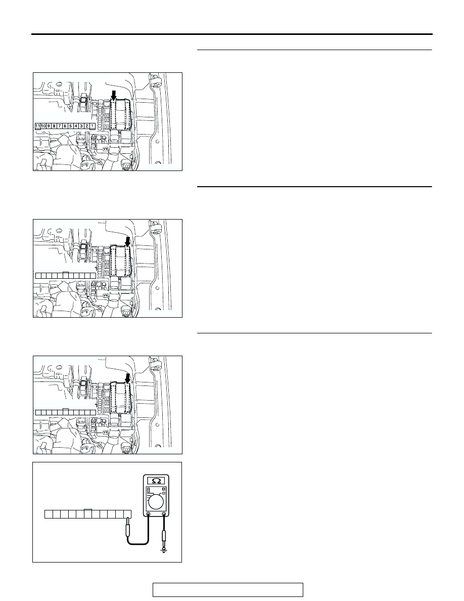
STEP 6. Check the ground circuit to the front-ECU. 
Measure the resistance at front-ECU connector A-12X.

(1) Disconnect front-ECU connector A-12X and measure the 

resistance available at the relay box side of the connector.

(2) Measure the resistance value between terminal 21 and 

ground.

• The resistance should be 2 ohms or less.

Q: Is the measured resistance 2 ohms or less?

YES : Go to Step 8.
NO :  Go to Step 7.

AC305977AH

CONNECTOR: A-11X

RELAY BOX SIDE 

AC305977

CONNCTOR: A-12X

AI

21

22

23

24

25

26

27

28

29

30

31

RELAY BOX SIDE

AC305977

CONNCTOR: A-12X

AI

21

22

23

24

25

26

27

28

29

30

31

RELAY BOX SIDE

AC209364CM

CONNECTOR A-12X
(RELAY BOX SIDE)

24

29

30

31

28 27

25

26

21

23 22

SYMPTOM PROCEDURES

TSB Revision

SIMPLIFIED WIRING SYSTEM (SWS)

54B-92

STEP 7. Check the wiring harness between front-ECU 
connector A-12X (terminal 21) and ground.

Q: Is the wiring harness between front-ECU connector 

A-12X (terminal 21) and ground in good condition?
YES : 
No action is necessary and testing is complete.
NO :  The wiring harness may be damaged or the 

connector(s) may have loose, corroded or damaged 
terminals, or terminals pushed back in the connector. 
Repair the wiring harness as necessary. The system 
should communicate with the front-ECU normally.

STEP 8. Check ETACS-ECU connector C-218 for loose, 
corroded or damaged terminals, or terminals pushed back 
in the connector.

Q: Is ETACS-ECU connector C-218 in good condition?

YES : Go to Step 9.
NO :  Repair or replace the damaged component(s). Refer 

to GROUP 00E, Harness Connector Inspection 

P.00E-2

. The system should communicate with the 

front-ECU normally.

STEP 9. Check the wiring harness between front-ECU 
connector A-12X (terminal 30) and ETACS-ECU connector 

C-218 (terminal 59).

AC305977

CONNCTOR: A-12X

AI

21

22

23

24

25

26

27

28

29

30

31

RELAY BOX SIDE

AC305413AN

CONNECTOR: C-218

JUNCTION BLOCK
(REAR VIEW)

C-218 (GR)

HARNESS SIDE

51

52

53

54

55

56

57

58

59

60

61

62

63

64

65

66

67

68

69

70

71

72

73

74

AC305977

CONNCTOR: A-12X

AI

21

22

23

24

25

26

27

28

29

30

31

RELAY BOX SIDE

AC305413AN

CONNECTOR: C-218

JUNCTION BLOCK
(REAR VIEW)

C-218 (GR)

HARNESS SIDE

51

52

53

54

55

56

57

58

59

60

61

62

63

64

65

66

67

68

69

70

71

72

73

74

SYMPTOM PROCEDURES

TSB Revision

SIMPLIFIED WIRING SYSTEM (SWS)

54B-93

NOTE: Also check joint connector C-03 and intermediate con-
nector C-29 for loose, corroded, or damaged terminals, or ter-
minals pushed back in the connector. If joint connector C-03 or 
intermediate connector C-29 is damaged, repair or replace the 
connector as described in GROUP 00E, Harness Connector 
Inspection 

P.00E-2

.

Q: Is the wiring harness between front-ECU connector 

A-12X (terminal 30) and ETACS-ECU connector C-218 
(terminal 59) in good condition?
YES : 
Go to Step 10.
NO :  The wiring harness may be damaged or the 

connector(s) may have loose, corroded or damaged 
terminals, or terminals pushed back in the connector. 
Repair the wiring harness as necessary. The system 
should communicate with the front-ECU normally.

STEP 10. Replace the front-ECU.
(1) Replace the front-ECU.
(2) The system should communicate with the front-ECU 

normally.

Q: Can the system communicate with the front-ECU?

YES : No action is necessary and testing is complete.
NO :  Replace the ETACS-ECU. The system should 

communicate with the front-ECU normally.

AC305232

CONNECTOR: C-03, C-29

C-03

C-29

C-03

C-29

AL

SYMPTOM PROCEDURES

TSB Revision

SIMPLIFIED WIRING SYSTEM (SWS)

54B-94

INSPECTION PROCEDURE A-5: Communication with the Sunroof-ECU is not Possible.

IGNITION
SWITCH (IG2)

SUNROOF MOTOR 
ASSEMBLY

SUNROOF-ECU

ETACS-ECU

FUSIBLE
LINK

5

JOINT 
CONNECTOR 
(2)

JUNCTION 
BLOCK

JUNCTION 
BLOCK

Sunroof Motor Assembly (Sunroof-ECU) and SWS Communication Circuit


Content   ..  223  224  225  226   ..