Mitsubishi Galant (2004+). Manual - part 1691


  Index      Mitsubishi     Mitsubishi Galant - service repair manual 2004 year


Search            


Content   ..  1689  1690  1691  1692   ..


Mitsubishi Galant (2004+). Manual - part 1691


OPERATION

CONTROLLER AREA NETWORK (CAN)

54C-3

OPERATION

M2542000300045

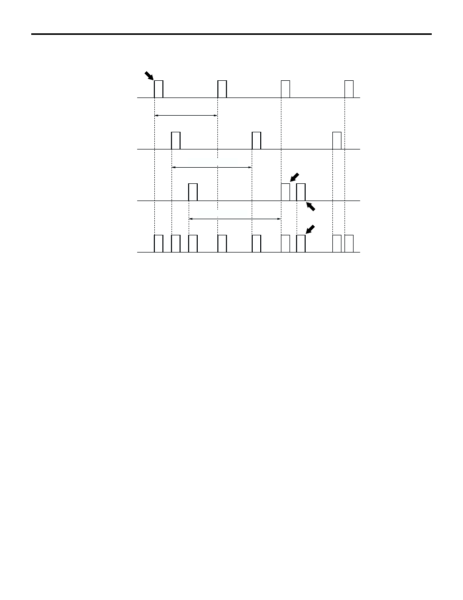
The CAN communication system is described below.

Data from each sensor is transmitted periodically 
as data frames over the CAN bus (periodically 
sent data). For further details, consult the Data 
Frame section.

The multiple ECUs requiring data over the CAN 
bus simultaneously receive data.

Transmission intervals from 10 to 1000 msec can 
be set, depending on the necessity of the data 
sent.
NOTE: In the figure above, the data frame A is 
transmitted in "a" intervals, while the data frames 
B and C are transmitted at intervals "b" and "c," 
respectively.

A single ECU transmits multiple data frames.

In the case of data collision (if multiple ECUs 
transmit at roughly the same moment), mediation 
occurs so that multiple data frames are not trans-
mitted simultaneously. For further details, consult 
the Mediation section .

Transmission is performed on the basis of electric 
potential difference, not through voltage as in 
conventional systems. For further details, consult 
the section on CAN bus voltage transformation.

Various kinds of error detection and recovery pro-
cessing are performed to secure a greater level 
of reliability. For further details, consult the sec-
tions on error detection and system recovery.

For further details on the main communication 
signals, consult the table on 

P.54C-6

.

.

MEDIATION
Because each ECU transmits data independently 
over the CAN bus, there are cases of data collision 
when multiple data frames that ECUs attempt to 
transmit simultaneously (if multiple ECUs transmit at 
roughly the same moment). When this happens, pro-
cessing of the ECUs attempting transmission is prior-
itized as follows:

1. Data frames with high-priority ID codes are 

granted transmission priority.

2. Transmission of low-priority data is held at the 

issuing ECUs until the bus clears (when no trans-
mission data exists on the CAN bus).
NOTE: In the holding state, new data (as the data 
frame content) will be sent after refreshing at 
fixed periods.

3. When the bus clears, the data frames are sent 

again.

NOTE: Because there is ample leeway on the CAN 
bus, there is no instance when data frames cannot 
be sent.

.

AC206267

ECU-1

A

A

A

A

B

B

B

C

C

A

B

C

C

C

B

B

A

A

A

ECU-2

ECU-3

CAN BUS

AC206267AB

DATA FRAME

INTERVAL a

INTERVAL b

INTERVAL c

SENT 
AGAIN

HELD 
COMMUNICATION 
BY MEDIATION

OPERATION

CONTROLLER AREA NETWORK (CAN)

54C-4

VOLTAGE TRANSFORMATION ON THE CAN BUS

Data frame transmission over the CAN bus line 
involves voltage transformation (for output signals) in 
the distinctive CAN profile shown in the figure below. 
The ECU transmitting over the CAN_H and CAN_L 
bus lines sends 2.5-3.5V signals to the CAN_H side 
and 2.5-1.5V signals to the CAN_L side. The receiv-
ing ECU reads the data from the CAN_H and CAN_L 
potential difference. Both CAN_H and CAN_L call 
2.5V states recessive. CAN_H calls 3.5V states dom-

inant while CAN_L calls 1.5V states dominant. By 
transformation mainly to 2.5V, even in cases when 
voltage is rendered 0 from faulty grounding or the 
like (causing a problem of an approximate 0.5 volt-
age increase on the communications line), communi-
cation can be continued uninterrupted. By 
incorporating dual communications lines, reliability in 
the presence of noise is greatly improved.

.

DATA FRAMES

SOF (Start of Frame)

Indicates the start of the frame

ID (Identifier) region

Specifies priority rank in case of mediation

Control region

Specifies the frame type, data length, etc.

Data region

Values used for data control, etc.

Cyclic Redundancy Check (CRC) region

Region for checking for errors in error content. 
The transmitter ECU calculates the value 
between SOF and data region by applying pre-
scribed operations and maintains the results. The 
receiving ECU detects erroneous communication 
by comparing the CRC region with the data 
region.

ACK (Acknowledge) region

Region for signal reception confirmation

EOF (End of Frame)

Indicates the end of the frame

.

AC306666

3.5V

2.5V

1.5V

0

1

AB

RECESSIVE

RECESSIVE

DOMINANT

VOLTAGE TRNSFORMATION 
ON CAN _H

VOLTAGE TRNSFORMATION 
ON CAN _L

LOGICAL VALUE:

CONDITION:

AC306667

S

O

F

E

O

F

AB

DATA REGION

ACK 
REGION

CRC 
REGION

ID 
REGION

DATA FRAME

CONTROL 
REGION

SELF-DIAGNOSIS

CONTROLLER AREA NETWORK (CAN)

54C-5

Error Detection and Recovery
The CAN protocol ensures communication reliability 
through the CRC that appears in data frames and 
through various error detection and recovery func-
tions (designed for recovery by retransmission, etc.). 
If an error is detected but it is not resolved even after 
recovery, communication is stopped. This state is 
called "Bus Off."

SELF-DIAGNOSIS

M2542000400042

CAN self-diagnosis is performed by each ECU 
connected to the CAN bus.

Diagnostic trouble codes related to communica-
tion are named with the capital letter U, and are 
called "U-codes."

A summary of the CAN self-diagnosis system is 
presented below. For further details on each 
diagnostic trouble code stored by the ECUs, con-
sult the U-Code Diagnostic Trouble Code List on 

P.54C-8

.

.

Time-out
Each ECU transmits data frames periodically. If the 
data frame is not received within the specified period, 
the intended receiving ECU transmits a diagnostic 
trouble code indicating communication time-out for 
the ECU that failed to transmit.

.

Bus off
Related to a communication error that persists even 
after the transmitting ECU attempts recovery for a 
specified number of attempts or that persists for a 
specified period after recovery. Communication is 
stopped and this diagnostic code is issued.

.

Failure data
When the transmitting ECU detects failure of a sen-
sor directly connected to it, this is the pertinent data 
used to inform the ECU.

.

Data length error
When the number of data bytes received is different 
from the prescribed number of bytes, this diagnostic 
trouble code is issued.

.

Dynamic range error
When the data received exceeds or is less than the 
prescribed range, this diagnostic trouble code is 
issued.

CAN BUS DIAGNOSTICS

M2542000500049

Because each ECU is interconnected through the 
CAN bus (where the MUT-III is also connected), the 
CAN bus must be diagnosed during inspection. Sim-
ply by performing MUT-III screen operations, the fol-
lowing inspections can be performed automatically, 
and the result can be used to verify the CAN bus sta-
tus.

Voltage measurement between the CAN_L and 
CAN_H and the body grounding terminal

Resistance measurement between the CAN_L 
and CAN_H

Confirmation of communication of all ECUs

CAN COMMUNICATION SIGNAL TABLE

CONTROLLER AREA NETWORK (CAN)

54C-6

CAN COMMUNICATION SIGNAL TABLE

M2542000600046

SIGNAL

TRANSMITTER 
ECU

RECEIVER ECU

POWERTRAIN 
CONTROL 
MODULE

ABS-ECU

MULTI-CENTER 
DISPLAY UNIT 
(MIDDLE-GRADE 
TYPE)

COMBINATION 
METER

A/C-ECU

ETACS-ECU

Engine speed signal

Powertrai
n control 
module

×

×

×

A/C information signal

×

Vehicle speed signal

×

×

Vehicle stop signal

×

×

×

×

Malfunction indicator 
lamp request signal

×

Auto-cruise control 
indicator lamp signal

×

Engine coolant 
temperature signal

×

×

Selector position signal

×

×

×

×

ABS warning light 
request signal

ABS-ECU

×

SRS warning light 
request signal

SRS-ECU

×

Communication 
continuation request 
signal

Multi-cent
er display 
unit 
(middle-gr
ade type)

×

×

Ignition switch (ACC) 
signal

×

×

Adjustment request 
signal

×

×

Customize signal

×

×

Tone alarm sound 
signal

×

×

Communication 
continuation request 
signal

Combinati
on meter

×

Vehicle speed signal

×

Ignition switch (IG1) 
signal

×

Seat belt signal

×

Fuel information signal

×


Content   ..  1689  1690  1691  1692   ..