Content .. 1565 1566 1567 1568 ..
Mitsubishi Galant (2004+). Manual - part 1567
SRS AIR BAG DIAGNOSIS
TSB Revision
SUPPLEMENTAL RESTRAINT SYSTEM (SRS)
52B-161
DTC B1431: Side-Airbag Module (LH) (Squib) System Fault 2 (Open in the Squib Circuit)
CAUTION
If DTC B1431 is set in the combination meter,
always diagnose the CAN bus lines.
.
CIRCUIT OPERATION
• The SRS-ECU judges how severe a collision is
by detecting signals from the left and right side
impact sensors. If the impact is over a predeter-
mined level, the SRS-ECU sends an ignition sig-
nal. At this time, if the side-airbag safing
G-sensor is on, the SRS side-airbag will inflate.
• The ignition signal is input to the side-airbag
module to inflate the side-airbag.
.
DTC SET CONDITIONS
This DTC is set if there is abnormal resistance
between the input terminals of the side-airbag mod-
ule (LH) (squib).
.
TROUBLESHOOTING HINTS
• Open circuit in the side-airbag module (squib)
(LH) circuit
• Improper connector contact
• Malfunction of the SRS-ECU
.
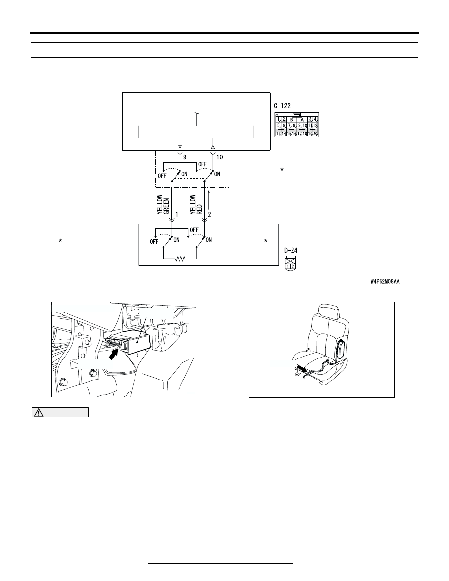
SIDE AIR BAG
MODULE
(SQUIB) (LH)
AIR BAG DRIVE CIRCUIT
SRS-ECU
CONNECTOR
LOCK SWITCH
CONNECTOR
LOCK SWITCH
Side-Airbag Module (LH) (Squib) Circuit
NOTE
: CONNECTOR
CONNECTED
: ON
CONNECTOR
DISCONNECTED
: OFF
AC305362
CONNECTOR: C-122
C-122 (Y)
AE
SRS-ECU
AC307778
CONNECTOR : D-24
AB
D-24 (R)