Mitsubishi Galant (2004+). Manual - part 1565


  Index      Mitsubishi     Mitsubishi Galant - service repair manual 2004 year


Search            


Content   ..  1563  1564  1565  1566   ..


Mitsubishi Galant (2004+). Manual - part 1565


SRS AIR BAG DIAGNOSIS

TSB Revision

SUPPLEMENTAL RESTRAINT SYSTEM (SRS)

52B-153

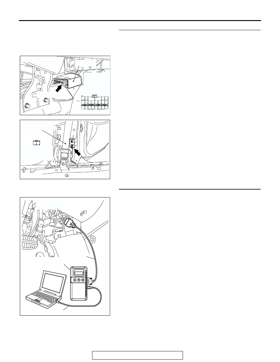
STEP 4. Check the harness wires for open circuit or short 
circuit between SRS-ECU connector C-120 (terminal No.63 
and 64) and side impact sensor (RH) connector D-35 
(terminal No.1 and 2).

Q: Are the harness wires between SRS-ECU connector 

C-120 (terminal No.63 and 64) and side impact sensor 
(RH) connector D-35 (terminal No.1 and 2) in good 
condition?
YES : 
Erase the diagnostic trouble code memory, and check 

the diagnostic trouble code. If DTC B1428 or B1429 
sets, replace the SRS-ECU. (Refer to 

P.52B-365

). 

Then go to Step 5.

NO :  Replace the harness wires between SRS-ECU 

connector C-120 and side impact sensor (RH) 
connector D-35. Then go to Step 5.

STEP 5. Recheck for diagnostic trouble code.

Check again if the DTC is set.
(1) Erase the DTC.
(2) Turn the ignition switch to the "ON" position.

(3) Check if the DTC is set.
(4) Turn the ignition switch to the "LOCK" (OFF) position.
Q: Is DTC B1428 or B1429 set?

YES : Return to Step 1.
NO :  The procedure is complete.

AC305362

CONNECTOR: C-120

C-120 (Y)

AG

SRS-ECU

63

55

51

69

61

66

58

65

64

56 57

68

60

67

59

70

62

53

52 B

A

54

C-120 
Harness side
connector 
(rear view)

AC308163

CONNECTOR: D-35

AC

FRONT SEAT BELT

2

1

HARNESS SIDE
CONNECTOR
(REAR VIEW)

AC305412

AB

MB991910

DATA LINK

CONNECTOR

MB991824

MB991827

SRS AIR BAG DIAGNOSIS

TSB Revision

SUPPLEMENTAL RESTRAINT SYSTEM (SRS)

52B-154

DTC B1430: Side-Airbag Module (LH) (Squib) System Fault 1 (Short Circuit between Terminals of the 
Squib Circuit)

CAUTION

If DTC B1430 is set in the combination meter, 
always diagnose the CAN bus lines.

.

CIRCUIT OPERATION

• The SRS-ECU judges how severe a collision is 

by detecting signals from the left and right side 
impact sensors. If the impact is over a predeter-
mined level, the SRS-ECU sends an ignition sig-
nal. At this time, if the side-airbag safing 
G-sensor is on, the SRS side-airbag will inflate.

• The ignition signal is input to the side-airbag 

module to inflate the side-airbag.

.

DTC SET CONDITIONS
This DTC is set if there is abnormal resistance 
between the input terminals of the side-airbag mod-
ule (LH) (squib).

.

TROUBLESHOOTING HINTS

• Improper engaged connector or defective short 

spring*

• Short circuit between the side-airbag module 

(LH) (squib) circuit terminals

• Damaged connector(s)

• Malfunction of the SRS-ECU

SIDE AIR BAG
MODULE
(SQUIB) (LH)

AIR BAG DRIVE CIRCUIT

SRS-ECU

CONNECTOR
LOCK SWITCH

CONNECTOR
LOCK SWITCH

Side-Airbag Module (LH) (Squib) Circuit

NOTE
  : CONNECTOR
    CONNECTED
    : ON
    CONNECTOR
    DISCONNECTED
    : OFF

AC305362

CONNECTOR: C-122

C-122 (Y)

AE

SRS-ECU

AC307778

CONNECTOR : D-24

AB

D-24 (R)

SRS AIR BAG DIAGNOSIS

TSB Revision

SUPPLEMENTAL RESTRAINT SYSTEM (SRS)

52B-155

NOTE:  *: The squib circuit connectors integrate a 
"short" spring (which prevents the air bag from 
deploying unintentionally due to static electricity by 
shorting the positive wire to the ground wire in the 
squib circuit when the connectors are disconnected). 
(Refer to 

P.52B-3

). Therefore, if connector C-122 or 

D-24 is damaged or improperly engaged, the short 
spring may not be released when the connector is 
connected.

.

DIAGNOSIS

Required Special Tools:

•  MB991958: Scan Tool (MUT-III Sub Assembly)

• MB991824: Vehicle Communication Interface (V.C.I.)

• MB991827: MUT-III USB Cable

• MB991910: MUT-III Main Harness A (Vehicles with CAN 

communication system)

• MB991865: Dummy resistor

• MB991866: Resister harness

STEP 1. Using scan tool MB991958, diagnose the CAN bus 
line.

CAUTION

To prevent damage to scan tool MB991958, always turn the 
ignition switch to the "LOCK" (OFF) position before con-
necting or disconnecting scan tool MB991958.
(1) Connect scan tool MB991958. Refer to "How to connect the 

scan tool 

P.52B-30

."

(2) Connect scan tool MB991958 to the data link connector.
(3) Turn the ignition switch to "ON" position.
(4) Diagnose the CAN bus line.
Q: Is the check result satisfactory?

YES : Go to Step 2
NO :  Repair the CAN bus lines (Refer to GROUP 54C, 

Diagnosis-Can Bus Diagnostic Chart 

P.54C-14

).

AC305412

AB

MB991910

DATA LINK

CONNECTOR

MB991824

MB991827

SRS AIR BAG DIAGNOSIS

TSB Revision

SUPPLEMENTAL RESTRAINT SYSTEM (SRS)

52B-156

STEP 2. Recheck for diagnostic trouble code.

Check again if the DTC is set.
(1) Erase the DTC.
(2) Turn the ignition switch to "ON" position.
(3) Check if the DTC is set.
(4) Turn the ignition switch to the "LOCK" (OFF) position.
Q: Is the DTC set?

YES : Go to Step 3.
NO :  There is an intermittent malfunction such as poor 

engaged connector(s) or open circuit (Refer to 
GROUP 00, How to Cope with Intermittent 
Malfunction 

P.00-6

).

STEP 3. Using scan tool MB991958, read the diagnostic 
trouble code.

CAUTION

To prevent damage to scan tool MB991958, always turn the 
ignition switch to the "LOCK" (OFF) position before con-
necting or disconnecting scan tool MB991958.
(1) Turn the ignition switch to the "ON" position.
(2) Check if the DTC is set.

(3) Turn the ignition switch to the "LOOK (OFF)" position.
Q: Is DTC B1519 set?

YES : Go to Step 4.
NO :  Go to Step 5.

AC305412

AB

MB991910

DATA LINK

CONNECTOR

MB991824

MB991827

AC305412

AB

MB991910

DATA LINK

CONNECTOR

MB991824

MB991827


Content   ..  1563  1564  1565  1566   ..