Mitsubishi Galant (2004+). Manual - part 1495


  Index      Mitsubishi     Mitsubishi Galant - service repair manual 2004 year


Search            


Content   ..  1493  1494  1495  1496   ..


Mitsubishi Galant (2004+). Manual - part 1495


RADIO WITH CD PLAYER

TSB Revision

CHASSIS ELECTRICAL

54A-223

INSTALLATION SERVICE POINTS

.

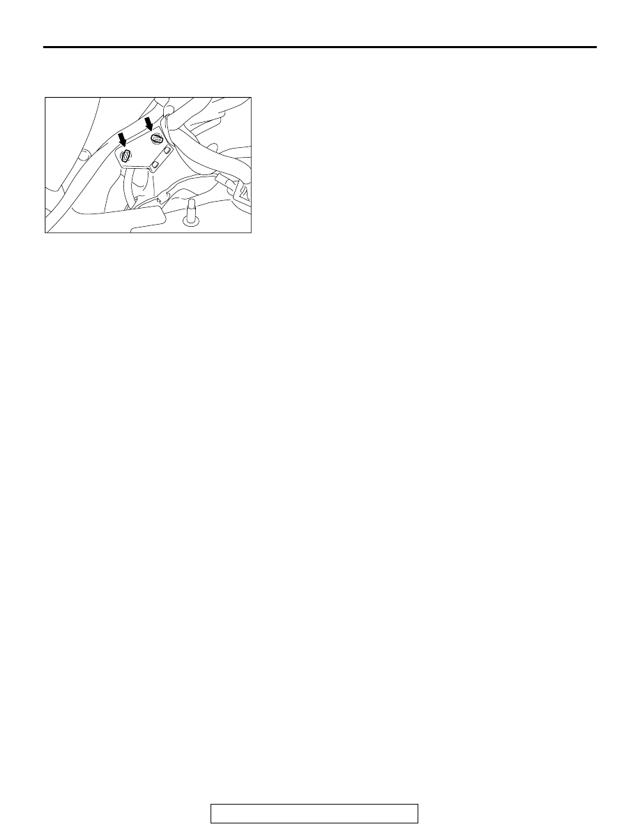
>>A<< AMPLIFIER INSTALLATION
Install while aligning with the amplifier mounting hole.

AC307132AB

RADIO WITH CD PLAYER

TSB Revision

CHASSIS ELECTRICAL

54A-224

ANTENNA

REMOVAL AND INSTALLATION

M1544002900552

WARNING

When removing and installing the passenger seat, be sure to carry out advanced air bag spe-
cial function (accuracy testing and calibration) after the seat has been installed in the vehi-
cle. (Refer to GROUP 52B, On-Vehicle Service 

P.52B-354

.)

AC306706

1

1.5 ± 0.5 N·m 
14 ± 4 in-lb

AB

REMOVAL STEPS

REAR SEAT CUSHION ASSEMBLY 
(GROUP 52A, REAR SEAT ASSEMBLY 

P.52A-30

.)

REAR SCUFF PLATE, FRONT DOOR 
OPENING TRIM (CENTER PILLAR 
SIDE), REAR DOOR OPENING TRIM 
(CENTER PILLAR SIDE), FRONT 
SCUFF PLATE (REFER TO GROUP 
52A, TRIMS 

P.52A-10

.)

FRONT SEAT BELT UPPER AND 
LOWER CONNECTION  (REFER TO 
GROUP 52A, FRONT SEAT BELT 

P.52A-33

.)

CENTER PILLAR TRIM LOWER, COWL 
SIDE TRIM (REFER TO GROUP 52A, 
TRIMS 

P.52A-10

.)

GEARSHIFT LEVER PANEL, FRONT 
BOX, FLOOR CONSOLE ASSEMBLY 
(REFER TO GROUP 52A, FLOOR 
CONSOLE ASSEMBL

P.52A-9

.)

FRONT SEAT ASSEMBLY (REFER TO 
GROUP 52A, FRONT SEAT ASSEMBLY 

P.52A-21

.)

TRUNK LID RELEASE HANDLE 
COVER (REFER TO GROUP 42, 
TRUNK LID 

P.42-64

.)

REMOVAL STEPS (Continued)

DEFOGGER

TSB Revision

CHASSIS ELECTRICAL

54A-225

DEFOGGER

GENERAL DESCRIPTION

M1543000100353

Defogger operation

• The defogger relay turns ON if the defogger 

switch built-in the A/C-ECU is turned ON when 
the ignition switch is in the "ON" position. When 
the defogger relay turns ON, power is supplied to 
the defogger and the defogger is activated. The 
defogger comes with a timer function that causes 
the defogger switch to automatically turn OFF in 
about 17 minutes after the defogger switch is 
turned ON.

DEFOGGER DIAGNOSIS

M1543000701068

The defogger is controlled by the A/C-ECU. For trou-
bleshooting, refer to GROUP 55A, Manual A/C Diag-
nosis 

− Symptom Chart <Low Type>

P.55A-112

  or 

Symptom Chart <Middle Type>

P.55A-181

 .

ACCELERATOR STOPPER (REFER TO 
GROUP 17, ACCELERATOR CABLE 
AND PEDAL 

P.17-9

.)

FLOOR CARPET

RADIO AND CD PLAYER OR RADIO, 
CD PLAYER AND CD CHANGER 
(REFER TO 

P.54A-216

.)

REAR SEATBACK ASSEMBLY (REFER 
TO GROUP 52A, REAR SEAT 
ASSEMBLY 

P.52A-30

.)

REAR DOOR OPENING TRIM (REAR 
PILLAR SIDE), REAR PILLAR TRIM, 
REAR SHELF SPEAKER GARNISH, 
REAR SHELF TRIM (REFER TO 
GROUP 52A, TRIMS 

P.52A-10

.)

1. ANTENNA FEEDER CABLE (REAR 

PILLAR SIDE)

ANTENNA FEEDER CABLE CLAMP

2. ANTENNA FEEDER CABLE

REMOVAL STEPS (Continued)

DEFOGGER

TSB Revision

CHASSIS ELECTRICAL

54A-226

ON-VEHICLE SERVICE

PRINTED-HEATER LINES CHECK

M1543001800333

1. Run the engine at 2,000 r/min. Check the heater element 

with the battery at full.

2. Turn "ON" the rear window defogger switch. Measure the 

heater element voltage with an ohmmeter at the rear 
window glass center A. Condition is good if it indicates about 
6 V.

3. If 12 V is indicated at A, there is a break in the negative 

terminals from A. Move the test probe slowly to the negative 
terminal to detect where voltage changes suddenly (0V).

4. If 0 V is indicated at A, there is a break in the positive 

terminals from A. Defect where the voltage changes 
suddenly (12 V) in the same method described above.

AC002357AC

A

ACX00813

NORMAL CHARACTERSTIC CURVE

ABNORMAL CHARACTERSTIC CURVE

VOLTAGE

A (CENTER POINT)

APPROXIMATELY
                         6 V

NEGATIVE
TERMINAL

PRINTED 
HEATER
LINE

POSITIVE
TERMINAL

NEGATIVE
TERMINAL

PRINTED 
HEATER
LINE

POSITIVE
TERMINAL

OPENCIRCUIT 
POINT

VOLTAGE

AC


Content   ..  1493  1494  1495  1496   ..