Mitsubishi Galant (2004+). Manual - part 1478


  Index      Mitsubishi     Mitsubishi Galant - service repair manual 2004 year


Search            


Content   ..  1476  1477  1478  1479   ..


Mitsubishi Galant (2004+). Manual - part 1478


RADIO WITH CD PLAYER

TSB Revision

CHASSIS ELECTRICAL

54A-155

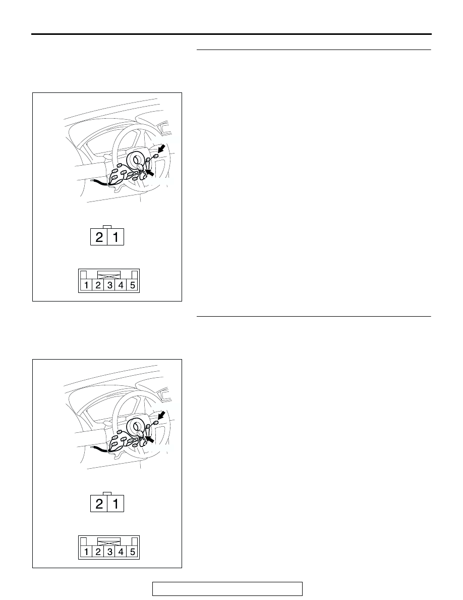
STEP 2. Check the remote controlled radio switch (RH) 
connector C-301 and clock spring connector C-303 for 
loose, corroded or damaged terminals, or terminals 
pushed back in the connector.
Q: Is remote controlled radio switch (RH) connector C-301 

and clock spring connector C-303 in good condition?
YES : 
Go to Step 3.
NO :  Repair or replace it. Refer to GROUP 00E, Harness 

Connector Inspection 

P.00E-2

. The remote controlled 

radio switch (RH) should work normally.

STEP 3. Check the wiring harness between remote 
controlled radio switch (RH) connector C-301 (terminals1 
and 2) and clock spring connector C-303 (terminals 4 and 
5).
Q: Are the wiring harness between remote controlled radio 

switch (RH) connector C-301 (terminals 1 and 2) and 
clock spring connector C-303 (terminals 4 and 5) in 
good condition?
YES : 
The procedure is complete.
NO :  Repair the wiring harness. The remote controlled 

radio switch (RH) should work normally.

AC305236

CONNECTORS: C-301, C-303

C-301 (B)

C-303 (GR)

C-301

C-303

HARNESS SIDE

AD

AC305236

CONNECTORS: C-301, C-303

C-301 (B)

C-303 (GR)

C-301

C-303

HARNESS SIDE

AD

RADIO WITH CD PLAYER

TSB Revision

CHASSIS ELECTRICAL

54A-156

INSPECTION PROCEDURE 4: The system does not recognize the remote controlled radio switch (LH) 
only.<Vehicles with Audio Amplifier>

.

CIRCUIT OPERATION
Refer to Inspection Procedure 2 

P.54A-145

.

.

TECHNICAL DESCRIPTION (COMMENT)
Refer to Inspection Procedure 2 

P.54A-145

.

.

TROUBLESHOOTING HINTS
Refer to Inspection Procedure 2 

P.54A-145

.

DIAGNOSIS

Required Special Tool:

• MB991223: Harness set

STEP 1. Measure the resistance at remote controlled radio 
switch (LH).
(1) Remove the airbag module assembly (Refer to GROUP 

52B, Air Bag Module(s) and Clock Spring 

P.52B-368

).

(2) Measure the resistance by operating the remote controlled 

radio switch (LH) in each position.

Q: Is the resistance at the left remote controlled radio 

switch normal?
YES : 
Go to Step 2.
NO :  Replace the remote controlled radio switch (LH).

SWITCH POSITION

MEASUREMENT VALUE

No push

Open circuit

Upper

Approximately 1.2 k

Center

Approximately 470 

Lower

Approximately 3.3 k

AC211693AB

RADIO WITH CD PLAYER

TSB Revision

CHASSIS ELECTRICAL

54A-157

STEP 2. Check the radio switch (LH) connector C-311 and 
clock spring connector C-303 for loose, corroded or 
damaged terminals, or terminals pushed back in the 
connector.
Q: Is remote controlled radio switch (LH) connector C-311 

and clock spring connector C-303 in good condition?
YES : 
Go to Step 3.
NO :  Repair or replace the connector. Refer to GROUP 

00E, Harness Connector Inspection 

P.00E-2

. The 

remote controlled radio switch (LH) should work 
normally.

STEP 3. Check the wiring harness between remote 
controlled radio switch connector C-311 (terminals1 and 2) 
and clock spring connector C-303 (terminals 4 and 5).
Q: Are the wiring harness between remote controlled radio 

switch connector C-311 (terminals 1 and 2) and clock 
spring connector C-303 (terminals 4 and 5) in good 
condition?
YES : 
No action to be taken.
NO :  Repair the wiring harness. The remote controlled 

radio switch (LH) should work normally.

AC305236

CONNECTORS: C-303, C-311

C-311 (B)

C-303 (GR)

C-303

C-311

HARNESS SIDE

AE

AC305236

CONNECTORS: C-303, C-311

C-311 (B)

C-303 (GR)

C-303

C-311

HARNESS SIDE

AE

RADIO WITH CD PLAYER

TSB Revision

CHASSIS ELECTRICAL

54A-158

INSPECTION PROCEDURE 5: No Sound. <Vehicles with Audio Amplifier>

.

CIRCUIT OPERATION
Power is supplied from the battery directly to the 
audio amplifier.

.

TECHNICAL DESCRIPTION (COMMENT)
The cause is probably a faulty audio amplifier power 
supply circuit system.

.

TROUBLESHOOTING HINTS

• Damaged wiring harness or connector.

• Malfunction of the audio amplifier.

FUSIBLE 
LINK

5

JUNCTION 
BLOCK

AUDIO AMPLIFIER

RADIO, CD PLAYER AND CD CHANGER

Audio Amplifier Power Supply Circuit

AC305231

CONNECTOR: C-29

AH

AC305233 CE

CONNECTORS: C-113, C-114, C-116

C-116

C-113

C-114


Content   ..  1476  1477  1478  1479   ..