Mitsubishi Galant (2004+). Manual - part 1466


  Index      Mitsubishi     Mitsubishi Galant - service repair manual 2004 year


Search            


Content   ..  1464  1465  1466  1467   ..


Mitsubishi Galant (2004+). Manual - part 1466


COMBINATION METER ASSEMBLY AND VEHICLE SPEED SENSOR

TSB Revision

CHASSIS ELECTRICAL

54A-107

Standard value <vehicles for CANADA>:

6. If not within the standard value, check the tire size. If an 

incorrect size of tire is used, replace it and check again. If 
the tire size is correct, a defect may be present in 
components and circuit between the output shaft speed 
sensor and the combination meter. Check the following 
items.

• output shaft speed sensor (refer to GROUP23A, Automatic 

Transaxle Diagnosis 

P.23A-91

).

• combination meter (refer to 

P.54A-87

.)

TACHOMETER CHECK

M1543001000456

Required Special Tools:

• MB991958: Scan Tool (MUT-III Sub Assembly)

• MB991824: Vehicle Communication Interface (V.C.I.)

• MB991827: MUT-III USB Cable

• MB991911: MUT-III Main Harness A (Vehicles with CAN 

communication system)
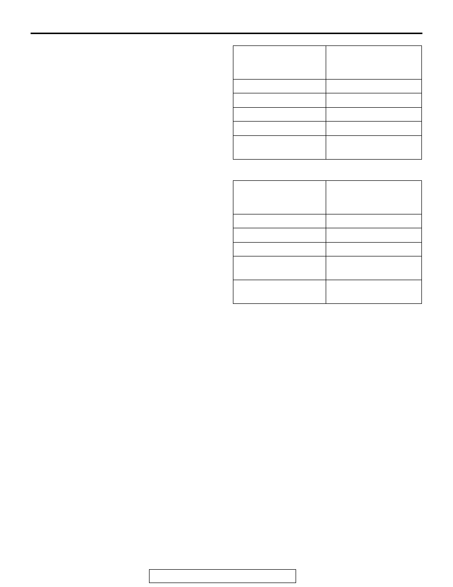
STANDARD 
INDICATION mph 
(km/h)

ALLOWANCE RANGE 
mph (km/h)

10 (16)

10 

± 1.5 (16 ± 2.4)

25 (40)

25 

± 1.5 (40 ± 2.4)

50 (80)

50 

± 1.5 (80 ± 2.4)

75 (120)

75 

± 1.5 (120 ± 2.4)

100 (161)

98.5 

− 102.5 (158.5 − 

165.0)

STANDARD 
INDICATION km/h 
(mph)

ALLOWANCE RANGE 
km/h (mph)

20 (12.4)

19 

− 24 (11.8 − 14.9)

40 (24.8)

40 

− 44 (24.8 − 27.3)

80 (49.7)

80 

− 85 (49.7 − 52.8)

120 (74.6)

120.5 

− 125.5 (74.9 − 

78.0)

160 (99.4)

160.5 

− 165.5 (99.7 − 

102.8)

COMBINATION METER ASSEMBLY AND VEHICLE SPEED SENSOR

TSB Revision

CHASSIS ELECTRICAL

54A-108

CAUTION

To prevent damage to scan tool MB991958, always turn the 
ignition switch to the "LOCK" (OFF) position before con-
necting or disconnecting scan tool MB991958.
1. Connect scan tool MB991958 to the data link connector.
2. A/T select lever: "P" position.
3. Turn the ignition switch to "ON" position.
4. Start the engine.
5. Run the engine.
6. Select MFI system data list and take a reading of the engine 

speed.

Item 22: CKP SENSOR

7. Compare the engine speed shown in the scan tool with that 

shown on the tachometer. The engine speeds shown on the 
tachometer should correspond to the table below.
NOTE: The following standard value assumes that battery 
voltage is 13.5 volts.

Standard value :

FUEL LEVEL SENSOR CHECK

M1543001300037

1. Remove the rear seat cusion assembly. (Refer to GROUP 

52A, Rear Seat Assembly 

P.52A-30

.)

2. Remove hole cover and remove the fuel pump module and 

fuel level sensor (sub).

Tightening torque: 1.5 

± 0.5 Nm (14 ± 0.5 in-Ib)

Engine speed (r/min)

Indication allowance of 
tachometer r/min

600

600 

± 100

2,000

2,000 

± 100

3,000

3,000 

± 150

4,000

4,000 

± 150

5,000

5,000 

± 150

6,000

6,000 

± 150

AC305412

AB

MB991910

DATA LINK

CONNECTOR

MB991824

MB991827

AC307098AB

FUEL PUMP MODULE

WIRING COVER

1.5 ± 0.5 N·m
14 ± 4 in-lb

FUEL LEVEL SENSOR (SUB)

COMBINATION METER ASSEMBLY AND VEHICLE SPEED SENSOR

TSB Revision

CHASSIS ELECTRICAL

54A-109

FUEL LEVEL SENSOR RESISTANCE

1. Check the resistances between  fuel level sensor main 

terminals 1 and 2 as well as sub terminals 1 and 2 of the fuel 
pump module, respectively.

Standard value:

2. Check that resistance value changes smoothly when the 

float moves slowly between points. 

3. If all checks are correct, go to fuel unit height check. If any 

check is not correct, replace the fuel pump module or fuel 
level sensor (sub).

FUEL LEVEL SENSOR FLOAT HEIGHT

1. Move the float and measure height A at point "F" (highest) 

and B at point "E" (lowest).

Standard value:

2. If any check is not correct, replace the fuel pump module or 

fuel level sensor (sub).

Items

Fuel level 
sensor 
(main)

fuel level 
sensor 
(sub)

Resistance 

Ω Point "F" 

(highest)

6.5 

± 1

6.5 

± 1

Point "E" 
(lowest)

44.6 

± 1

75.4 

± 1

AC307470

FUEL LEVEL SENSOR 
(MAIN)

FUEL LEVEL SENSOR 
(SUB)

F

E

E

F

AB

Items

Fuel level 
sensor 
(main)

Fuel level 
sensor (sub)

Height 
mm (in)

 A at point 
"F"

35.5 

± 3.0 

(1.4 

± 0.1)

25.0 

± 3.0 

(1.0 

± 0.1)

 B at point 
"E" 

133.7 

± 3.0 

(5.3 

± 0.1)

173.1 

± 3.0 

(68.1 

± 0.1)

AC207587

AC307022

FUEL LEVEL SENSOR (MAIN)

POINT "F"

POINT "E"

AB

A

B

AC307023

AB

A

B

FUEL LEVEL SENSOR (SUB)

POINT "F"

POINT "E"

COMBINATION METER ASSEMBLY AND VEHICLE SPEED SENSOR

TSB Revision

CHASSIS ELECTRICAL

54A-110

COMBINATION METER ASSEMBLY AND VEHICLE SPEED SENSOR

 REMOVAL AND INSTALLATION

M1543002900429

 DISASSEMBLY AND ASSEMBLY

M1543003100352

AC306952AB

COMBINATION METER

NOTE:
THE COMBINATION METER CONNECTOR IS FIXED IN THE INSTRUMENT PANEL.

AC205381

1

2

AC

DISASSEMBLY STEPS

1. WINDOW PLATE
2. METER ASSEMBLY


Content   ..  1464  1465  1466  1467   ..