Mitsubishi Galant (2004+). Manual - part 146


  Index      Mitsubishi     Mitsubishi Galant - service repair manual 2004 year


Search            


Content   ..  144  145  146  147   ..


Mitsubishi Galant (2004+). Manual - part 146


TIMING BELT

TSB Revision

ENGINE MECHANICAL <2.4L ENGINE>

11A-57

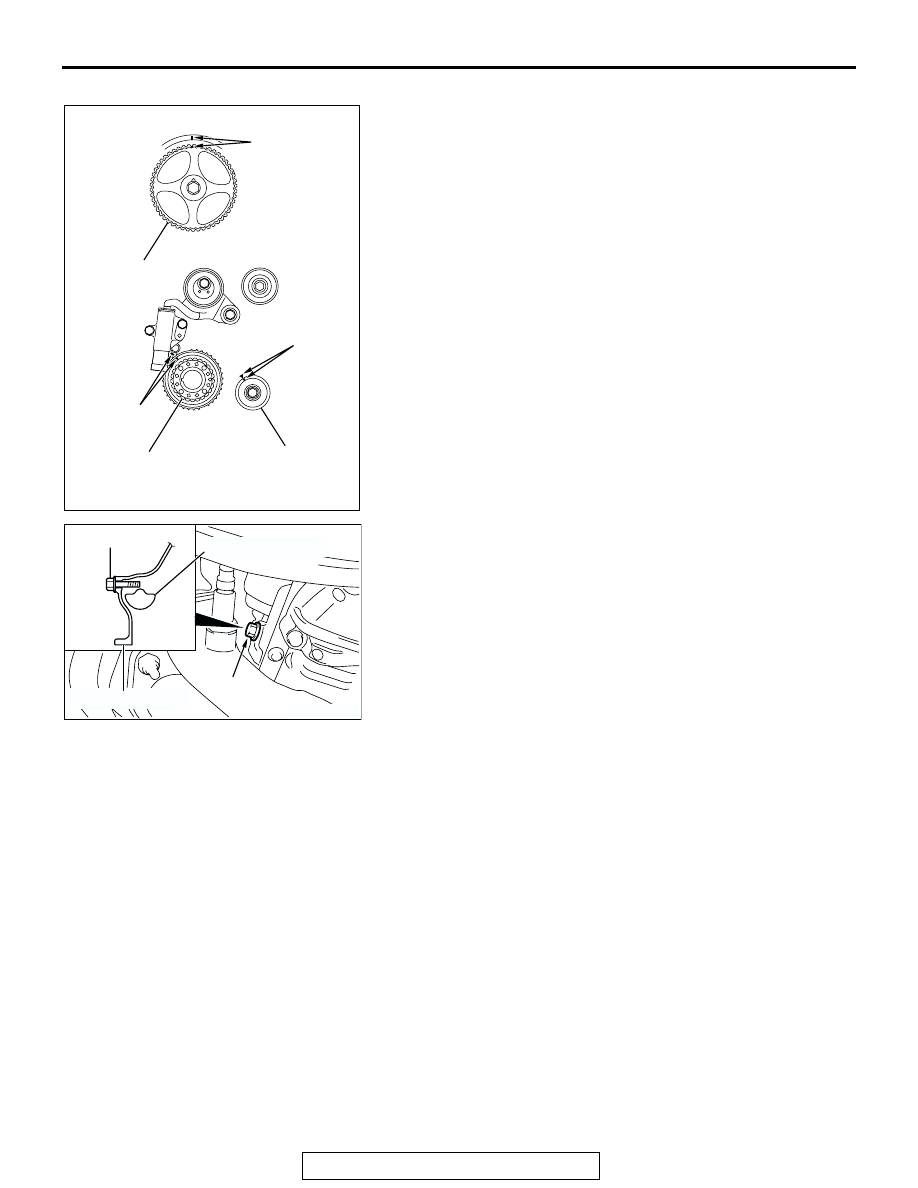
>>F<< VALVE TIMING BELT INSTALLATION
1. Align the timing marks on the camshaft sprocket, crankshaft 

camshaft drive sprocket and engine oil pump sprocket.

2. Adjust the timing mark of the engine oil pump sprocket. 

Unplug the cylinder block plug. Insert a bolt (M6, section 
width 10 mm, nominal length 45 mm) from the plug hole. If 
the bolt comes in contact with the balancer shaft, turn the 
engine oil sprocket one rotation. Re-adjust the timing mark 
and then check to see that the bolt fits. Do not remove the 
bolt until the valve timing belt is assembled.

AC301374

AB

TIMING MARK

TIMING 
MARK

TIMING 
MARK

CAMSHAFT 
SPROCKET

CRANKSHAFT 
CAMSHAFT 
DRIVE SPROCKET

ENGINE OIL 
PUMP SPROCKET

AC301871AB

PLUG

BOLT

BALANCERSHAFT

CYLINDER BLOCK

TIMING BELT

TSB Revision

ENGINE MECHANICAL <2.4L ENGINE>

11A-58

3. Incorporate the valve timing belt in the following manner so 

that the tensile force of the belt is not lax. 

(1) Place the valve timing belt on the timing belt tensioner 

pulley and crankshaft camshaft driver sprocket and then 
support it with your left hand so it does not slide.

(2) Place the valve timing belt on the engine oil pump 

sprocket while pulling it with the right hand.

(3) Place the valve timing belt on the timing belt idler pulley.

CAUTION

Incorporate the valve timing belt. Then apply reverse rota-
tion (counterclockwise rotation) pressure to the cam shaft 
sprocket. Re-check to see that each timing mark is aligned 
while the tension side of the belt is right.

(4) Place the valve timing belt on the camshaft sprocket.

4. Turn the timing belt tensioner pulley in the direction shown in 

the figure using special tool MD998767 to apply tension to 
the valve timing belt. Then temporarily tighten and fix the 
timing belt tensioner pulley mounting bolt.

5. Check that the timing marks are aligned.

AC301372

AC

TIMING BELT 
TENSIONER 
PULLEY

CAMSHAFT 
SPROCKET

CRANKSHAFT
CAMSHAFT 
DRIVE SPROCKET

ENGINE OIL
PUMP SPROCKET

BELT
TENSION 
SIDE

TIMING BELT 
IDLER PULLEY

AC301858

MD998767

AB

AC301372

AB

TIMING MARK

TIMING 
MARK

TIMING 
MARK

CAMSHAFT 
SPROCKET

CRANKSHAFT 
CAMSHAFT
DRIVE SPROCKET

ENGINE 
OIL PUMP 
SPROCKET

TIMING BELT

TSB Revision

ENGINE MECHANICAL <2.4L ENGINE>

11A-59

6.  Remove the bolt inserted in Step 2 above, then assemble 

the cylinder block plug.

7. Tighten the cylinder block plug to the specified torque.

Tightening torque: 30 

± 3 Nm (23 ± 2 ft-lb)

8. Adjust the valve timing belt tension.

.

>>G<< VALVE TIMING BELT TENSION ADJUSTMENT 
1. Set special tool MD998738 used when removing the valve 

timing belt.

CAUTION

Always screw in special tool MD998738 in with your hands, 
since use of a spanner or other tools may damage the wire 
or pin inserted in the timing belt tensioner adjuster. 
2. Gradually screw in special tool MD998738 to a position in 

which the wire or pin inserted in the timing belt tensioner 
adjuster lightly moves. 

3. Turn the crankshaft 1/4 of a revolution in the 

counterclockwise direction.

4. Turn the crankshaft in the clockwise direction, align each 

timing mark to set number 1 cylinder to TDC of its 
compression stroke.

5. Loosen the timing belt tensioner pulley mounting bolt.

AC301871AB

PLUG

BOLT

BALANCERSHAFT

CYLINDER BLOCK

AC301452AB

MD998738

TIMING BELT
UNDER COVER

AC301372

AB

TIMING MARK

TIMING 
MARK

TIMING 
MARK

CAMSHAFT 
SPROCKET

CRANKSHAFT 
CAMSHAFT
DRIVE SPROCKET

ENGINE 
OIL PUMP 
SPROCKET

TIMING BELT

TSB Revision

ENGINE MECHANICAL <2.4L ENGINE>

11A-60

CAUTION

When tightening the mounting bolt, ensure that the timing 
belt tensioner pulley does not rotate with the bolt. Allowing 
it to rotate with the bolt can cause deficient tension of the 
belt.
6. With special tool MD998767 and torque wrench, apply 

tension torque [3.5 N

⋅m (31 in-lb)] to the valve timing belt, 

and tighten the timing belt tensioner pulley mounting bolt to 
the specified torque.

Tightening torque: 48 

± 5 Nm (36 ± 3 ft-lb)

7. Remove wire or pin inserted to timing belt tensioner 

adjuster.

8. Remove special tool MD998738, and install the rubber plug 

to the timing belt under cover.

9. Rotate crankshaft clockwise two turns, and leave it for about 

15 minutes.

10.Insert wire or pin removed in Step 7 again, and ensure that it 

can be pulled out with a light load. When wire or pin can be 
lightly removed, appropriate tension is applied on timing 
belt. In this case, remove wire or pin.

AC301859

MD998767

AB

AC301857AB

WIRE OR PIN

AC301452AB

MD998738

TIMING BELT
UNDER COVER

AC301857AB

WIRE OR PIN


Content   ..  144  145  146  147   ..