Mitsubishi Galant (2004+). Manual - part 145


  Index      Mitsubishi     Mitsubishi Galant - service repair manual 2004 year


Search            


Content   ..  143  144  145  146   ..


Mitsubishi Galant (2004+). Manual - part 145


TIMING BELT

TSB Revision

ENGINE MECHANICAL <2.4L ENGINE>

11A-53

INSTALLATION SERVICE POINTS

.

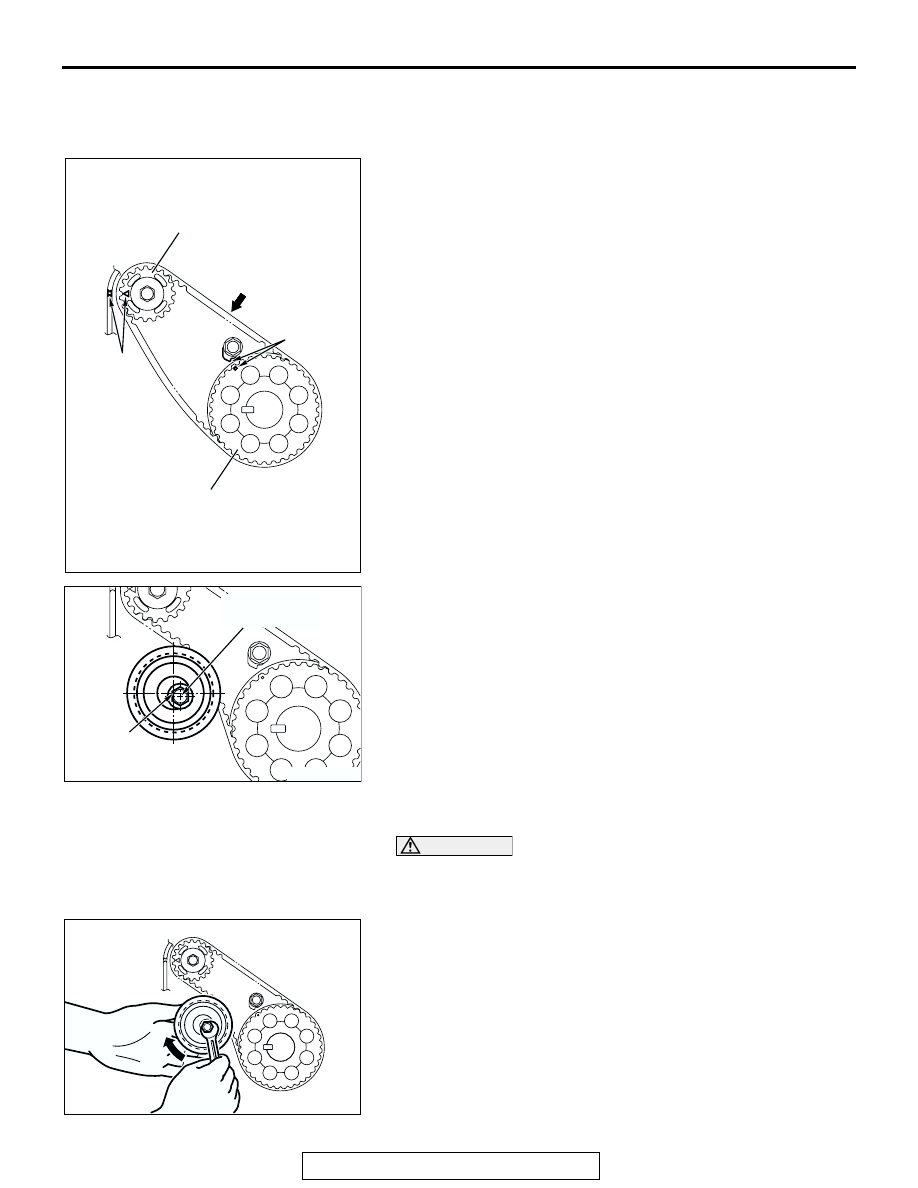
>>A<< BALANCER TIMING BELT/BALANCER TIMING 
BELT TENSIONER INSTALLATION
1. Ensure that the crankshaft balancer shaft drive sprocket 

timing marks and balancer shaft sprocket timing marks are 
aligned.

2. Install the balancer timing belt on the crankshaft balancer 

shaft drive sprocket and balancer shaft sprocket. There 
should be no slack on the tension side.

3. Assemble and temporarily fix the center of the pulley of the 

balancer timing belt tensioner so that it is at the top left from 
the center of the assembling bolt, and the pulley flange is at 
the front-side of the engine.

4. Adjust the balancer timing belt tension.

.

>>B<< BALANCER TIMING BELT TENSION ADJUSTMENT

CAUTION

When tightening the mounting bolts, ensure that the ten-
sioner does not rotate with the bolts. Allowing it to rotate 
with the bolts can cause excessive tension of the belt.
1. Lift with your fingers the balancer timing belt tensioner in the 

direction of the arrow. Apply a tensile torque of [3.0 

± 0.4 

N

⋅m (26 ± 4 in-lb)] to the balancer timing belt so the belt is 

tense without any looseness. Tighten the assembling bolt to 
the specified torque in this state. Then, fix the balancer 
timing belt tensioner.

Tightening torque: 19 

± 3 Nm (14 ± 2 ft-lb)

AC301402AB

TIMING 
MARK

TIMING 
MARK

CRANKSHAFT BALANCER 
SHAFT DRIVE SPROCKET

BALANCER SHAFT
SPROCKET

BELT TENSION 
SIDE

AC301403AB

CENTER OF 
THE PULLEY

CENTER OF THE 
MOUNTING BOLT

AC301404

TIMING BELT

TSB Revision

ENGINE MECHANICAL <2.4L ENGINE>

11A-54

2. Turn the crankshaft clockwise two turns to set number 1 

cylinder to TDC of its compression stroke and check that 
sprocket timing marks are aligned.

3. Apply a pressure of approximately 100 N (22 pounds) at the 

center (arrow area) between the sprocket as shown in the 
figure, then inspect whether the belt deflection is within the 
standard value.

Standard value:

<When adjusting> 5 

 7 mm (0.20  0.27 inch)

<When replacing> 5 

 7 mm (0.20  0.27 inch)

4. If not within the standard value, adjust the belt tension again.

.

AC301402AC

TIMING 
MARK

TIMING 
MARK

CRANKSHAFT BALANCER 
SHAFT DRIVE SPROCKET

BALANCER SHAFT
SPROCKET

AC301405AB

APPROXIMATELY
100 N (22 lb)

DEFLECTION

TIMING BELT

TSB Revision

ENGINE MECHANICAL <2.4L ENGINE>

11A-55

>>C<< CRANKSHAFT ANGLE SENSING 
BLADE/CRANKSHAFT CAMSHAFT DRIVE 
SPROCKET/CRANKSHAFT PULLEY 
WASHER/CRANKSHAFT PULLEY CENTER BOLT 
INSTALLATION
1. Clean or degrease the crankshaft, the crankshaft angle 

sensing blade, the crankshaft camshaft drive sprocket and 
crankshaft pulley washer as shown.
NOTE: Also clean the degreased surfaces.

2. Install the crankshaft angle sensing blade and crankshaft 

camshaft drive sprocket in the direction shown.

3. Place the larger chamfer side of the crank shaft pulley 

washer in the direction shown in the Figure and then 
assemble on the crank shaft pulley center bolt.

4. Apply a small of engine oil to the crank shaft pulley center 

bolt bearing surface and screw.

5. Hold the crankshaft camshaft drive sprocket with special 

tools MB991367 and MB991385 in the same manner as 
removal.

6. Tighten the crankshaft pulley center bolts to the specified 

torque.

Tightening torque: 167 N

m (123 ft-lb)

.

>>D<< TIMING BELT TENSIONER ADJUSTER 
INSTALLATION
1. Set according to the following procedures when the timing 

belt tensioner adjuster rod is fully extended.

AC301347

AB

ENGINE FRONT

CRANKSHAFT CAMSHAFT
DRIVE SPROCKET

CRANKSHAFT PULLEY 
CENTER BOLT

CRANKSHAFT 
PULLEY WASHER

CRANKSHAFT ANGLE
SENSING BLADE

CRANKSHAFT 

: CLEAN

: APPLY ENGINE OIL

: CLEAN AND DEGREASE

AC102332AB

MB991385

MB991367

CRANKSHAFT
CAMSHAFT
DRIVE 
SPROCKET

TIMING BELT

TSB Revision

ENGINE MECHANICAL <2.4L ENGINE>

11A-56

CAUTION

If the compression is too fast the procedure may damage 
the rod. Make a point to slowly and thoroughly compress.

(1) Slowly compress the timing belt tensioner adjuster rod 

using a press or vice, then align the set hole A of the rod 
with set hole B of the timing belt tensioner adjuster 
cylinder.

(2) Insert a wire or pin in the set hole aligned.

NOTE: When replacing the timing belt tensioner adjuster 
with new parts, the timing belt tensioner adjuster is set 
with a pin.

2. Install the timing belt tensioner adjuster to the engine and 

then tighten the mounting bolt to the specified torque. Do not 
remove the wire or pin until the tension of the valve timing 
belt is adjusted. 

Tightening torque: 23 

± 3 Nm (17 ± 2 ft-lb)

.

>>E<< TIMING BELT TENSIONER PULLEY INSTALLATION
Temporarily tighten the timing belt tensioner pulley as shown.

.

AC302024

A

AB

B

AC302025

WIRE OR PIN

AB

AC102336AB

TIMING BELT TENSIONER
PULLEY HOLE  


Content   ..  143  144  145  146   ..