Mitsubishi Galant (2004+). Manual - part 143


  Index      Mitsubishi     Mitsubishi Galant - service repair manual 2004 year


Search            


Content   ..  141  142  143  144   ..


Mitsubishi Galant (2004+). Manual - part 143


CYLINDER HEAD GASKET

TSB Revision

ENGINE MECHANICAL <2.4L ENGINE>

11A-45

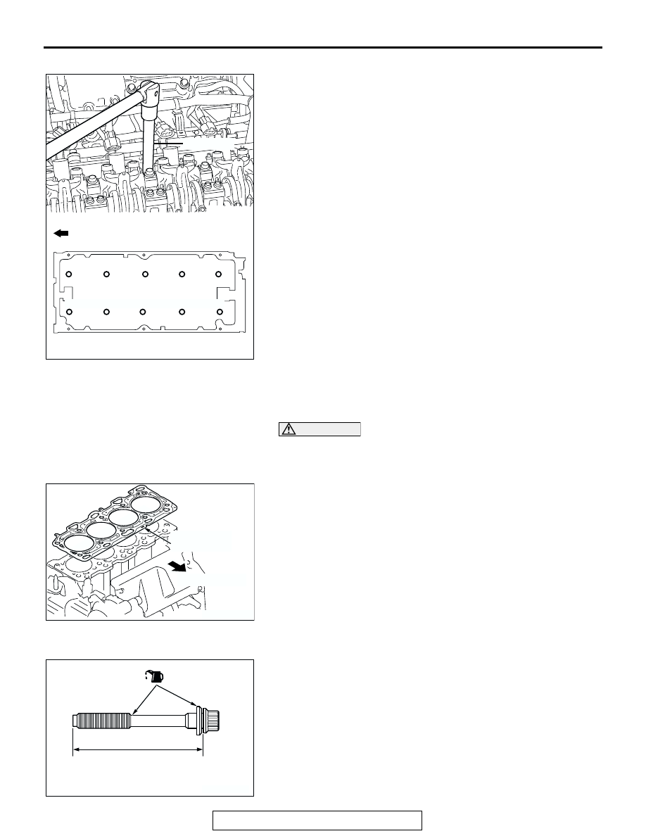
<<D>> CYLINDER HEAD BOLTS REMOVAL
Use special tool MB991654 to loosen the cylinder head bolts in 
two or three steps in the order of the numbers shown in the 
illustration. If the cylinder head bolts cannot be pulled out due 
to the washer being trapped in the valve spring, raise the bolt 
slightly, then remove it while holding it by using a magnet.

INSTALLATION SERVICE POINTS

.

>>A<< CYLINDER HEAD GASKET INSTALLATION

CAUTION

Do not allow any foreign materials get into the coolant pas-
sages, oil passages and cylinder.
1. Degrease the cylinder head gasket mounting surface.
2. Assemble to the cylinder block so the cylinder head gasket 

identification mark of "381" is at the top surface and on the 
exhaust side.

.

>>B<< CYLINDER HEAD BOLTS INSTALLATION
1. Check that the nominal length of each cylinder head bolt 

meets the limit. If it exceeds the limit, replace the bolts with a 
new one.

Limit (A): 99.4 mm (3.91 inches)

2. Apply a small amount of engine oil to the thread of the bolts 

and to the washers.

AC301454AB

ENGINE FRONT

MB991654

10

5

2

8

3

9

7

4

6

1

AC302180AB

IDENTIFICATION 
MARK "381"

EXHAUST SIDE

AC102537

A

AC

(ENGINE OIL)

CYLINDER HEAD GASKET

TSB Revision

ENGINE MECHANICAL <2.4L ENGINE>

11A-46

3. Use special tool MB991654 to tighten the cylinder head 

bolts in the following procedures.

(1) Tighten the bolts to 78 

± 2 N⋅m (58 ± 1 ft-lb) in the order 

shown.

(2) Loosen the bolts fully in the reverse sequence to that 

shown.

(3) Tighten the bolts to 20 

± 2 N⋅m (15 ± 1 ft-lb) in the order 

shown.

(4) Apply a paint mark to the heads of the cylinder head bolts 

and cylinder head, then tighten 90 degree angle as 
shown.

CAUTION

• The bolt is not tightening sufficiently if the tightening 

angle is less than a 90 degree angle.

• If the tightening angle exceeds the standard specifica-

tion, remove the bolt and start over from step 1.

(5) Tighten in a 90 degree angle as shown in the instructions 

of the figure, then check to see that the paint mark on the 
head of the cylinder head bolts and the paint mark on the 
cylinder head is on a linear line.

.

AC301456AB

ENGINE FRONT

MB991654

10

9

7

5

2

4

8

6

1

3

AC102331AB

PAINT MARKING

90˚

90˚

PAINT MARKING

STEP (4)

STEP (5)

CYLINDER HEAD GASKET

TSB Revision

ENGINE MECHANICAL <2.4L ENGINE>

11A-47

>>C<< FUEL HIGH-PRESSURE HOSE INSTALLATION

CAUTION

After connecting the fuel high-pressure hose, slightly pull 
it to ensure that it is installed securely. Also confirm that 
there is a play approximately 3 mm (0.12 inch). Then install 
the stopper securely.
Apply a small amount of engine oil to the fuel line pipe and then 
install the fuel high-pressure hose.

.

>>D<< RADIATOR UPPER HOSE CONNECTION
1. Insert radiator upper hose until it contacts the projection on 

the water outlet fitting.

2. Align the mating marks on the radiator upper hose and hose 

clamp, and then secure the radiator upper hose.

.

>>E<< CAMSHAFT SPROCKET INSTALLATION
1. Hold the camshaft sprocket with special tools MB990767 

and MD998719 in the same manner as removal.

2. Tighten the camshaft sprocket mounting bolt to the specified 

torque.

Tightening torque: 89 

± 9 Nm (65 ± 7 ft-lb)

.

AC301864AB

3 mm
(0.12 in)

FUEL 
HIGH-PRESSURE 
HOSE

FUEL LINE PIPE
(ENGINE OIL APPLIED)

AC304583

AB

STOPPER

AC200642

MATING
MARKS

PROJECTION

WATER OUTLET
FITTING

AB

AC102532 AB

MB990767

MD998719

CYLINDER HEAD GASKET

TSB Revision

ENGINE MECHANICAL <2.4L ENGINE>

11A-48

>>F<< BRAKE BOOSTER VACUUM HOSE CONNECTION
Insert vacuum hose with its paint mark facing upward.

AC305104

PAINT 
MARK

AB


Content   ..  141  142  143  144   ..