Mitsubishi Galant (2004+). Manual - part 1431


  Index      Mitsubishi     Mitsubishi Galant - service repair manual 2004 year


Search            


Content   ..  1429  1430  1431  1432   ..


Mitsubishi Galant (2004+). Manual - part 1431


STEERING SHAFT

TSB Revision

POWER STEERING

37A-33

ASSEMBLY SERVICE POINT

.

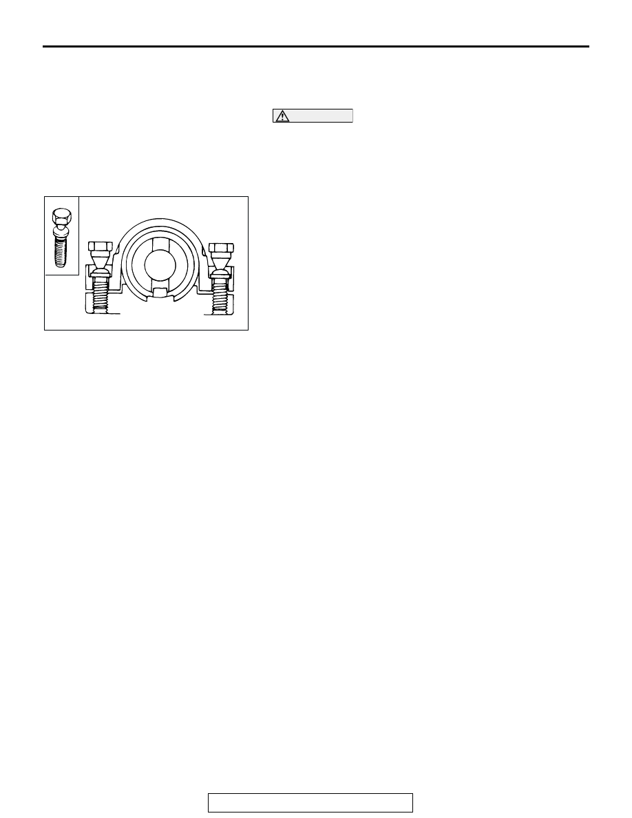
>>A<< ENGINE STARTING SWITCH ASSEMBLY/STEERING 
LOCK BOLT INSTALLATION

CAUTION

The bolts must be replaced with new ones when the steer-
ing lock is installed.
1. When installing the engine starting switch assembly to the 

steering column assembly, temporarily install the engine 
starting switch assembly in alignment with the column boss.

2. After checking that the lock works properly, tighten the 

steering lock bolts until the head is twisted off.

ACX01139 AB

POWER STEERING GEAR BOX AND LINKAGE

TSB Revision

POWER STEERING

37A-34

POWER STEERING GEAR BOX AND LINKAGE

REMOVAL AND INSTALLATION

M1372010900259

WARNING

Before removing the power steering gear assembly, refer to GROUP 52B, Service Precau-
tions and Air Bag Module and Clock Spring (

P.52B-26

 and 

P.52B-368

).

Center the front wheels. Failure to do so may damage the SRS clock spring and render the 
SRS system inoperative, risking serious injury.

CAUTION

*

: Indicates parts which should be temporarily tightened, and then fully tightened after placing the 

vehicle horizontally and loading the full weight of the engine on the vehicle body.

Pre-removal Operation
• Power Steering Fluid Draining (Refer to 

P.37A-21

).

• Front Under Cover Removal
• Centermember Removal (Refer to GROUP 32, Engine 

Roll Stopper and Centermember 

P.32-7

).

• Lower Arm Assembly Removal (Refer to GROUP 33A, 

Lower Arm 

P.33-15

).

• Air Bag Module and Steering Wheel Assembly Removal 

(Refer to 

P.37A-27

).

• Floor Console Assembly Removal (Refer to GROUP 52A, 

Floor Console Assembly 

P.52A-9

).

• Front Scuff Plate and Cowl Side Trim Removal (Refer to 

GROUP 52A, Trims 

P.52A-10

). 

• Trunk Lid Opener Cover Removal 
• Accelerator Pedal Stopper Removal 

• Front Floor Carpet Removal

• Stabilizer Link and Stabilizer Bar Disconnection (Refer to 

GROUP 33A, Stabilizer Bar 

P.33-20

).

Post-installation Operation
• Check the dust cover for cracks or damage by pushing it 

with your finger.

• Stabilizer Link and Stabilizer Bar Connection (Refer to 

GROUP 33A, Stabilizer Bar 

P.33-20

).

• Front Floor Carpet Installation

• Accelerator Pedal Stopper Installation 

• Trunk Lid Opener Cover Installation 
• Front Scuff Plate and Cowl Side Trim Removal (Refer to 

GROUP 52A, Trims 

P.52A-10

). 

• Floor Console Assembly Installation (Refer to GROUP 

52A, Floor Console Assembly 

P.52A-9

).

• Steering Wheel Assembly and Air Bag Module Installation 

(Refer to 

P.37A-27

).

• Checking Steering Wheel Position with Wheels Straight 

Ahead.

• Lower Arm Assembly Installation (Refer to GROUP 33A, 

Lower Arm 

P.33-15

).

• Centermember Installation (Refer to GROUP 32, Engine 

Roll Stopper and Centermember 

P.32-7

).

• Front Under Cover Installation

• Front Wheel Alignment Adjustment (Refer to GROUP 

33A, On-vehicle Service 

− Front Wheel Alignment Check 

and Adjustment 

P.33-6

).

• Power Steering Fluid Supplying (Refer to 

P.37A-21

).

• Power Steering Fluid Line Bleeding (Refer to 

P.37A-22

).

POWER STEERING GEAR BOX AND LINKAGE

TSB Revision

POWER STEERING

37A-35

Required Special Tool:

• MB991897: Ball Joint Remover

AC306567

2

18 ± 2 N·m
13 ± 2 ft-lb

29 ± 4 N·m
21 ± 3 ft-lb

9

8

3

4

5

15

1

58 ± 7 N·m
43 ± 5 ft-lb

17

83 ± 12 N·m
61 ± 9 ft-lb

15 ± 3 N·m
11 ± 2 ft-lb

12 ± 2 N·m
102 ± 22 in-lb

7

15 ± 3 N·m
11 ± 2 ft-lb

N

N

14

58 ± 7 N·m
43 ± 5 ft-lb

10

58 ± 7 N·m*
43 ± 5 ft-lb*

165 ± 15 N·m
122 ± 11 ft-lb

180 ± 20 N·m
133 ± 14 ft-lb

83 ±12 N·m
61 ± 9 ft-lb

12

13

16

AB

11

58 ± 7 N·m
43 ± 5 ft-lb

12 ± 2 N·m
102 ± 22 in-lb

7

8

REMOVAL STEPS

1. STEERING SHAFT PAD

<<A>>

2. STEERING COLUMN ASSEMBLY 

AND STEERING GEAR 
CONNECTION

<<B>>

3. SELF LOCKING NUT (TIE ROD END 

AND KNUCKLE CONNECTION)

4. RETURN TUBE CONNECTION
5. PRESSURE HOSE CONNECTION
6. RETURN TUBE CLAMP
7. PRESSURE HOSE CLAMP
8. O-RING
9. REAR ROLL STOPPER 

CONNECTING BOLT

>>C<<

10. SELF LOCKING NUT

<<C>> >>C<<

11. FRONT AXLE CROSSMEMBER 

STAY

<<D>> >>B<<

12. CROSSMEMBER ASSEMBLY

>>B<<

13. STEERING COLUMN DASH PANEL 

COVER

>>A<<

14. REAR ROLL STOPPER

>>A<<

15. POWER STEERING GEAR 

BRACKET

16. STEERING GEAR AND LINKAGE 

PROTECTOR <3.8L ENGINE>

17. POWER STEERING GEAR AND 

LINKAGE

REMOVAL STEPS (Continued)

POWER STEERING GEAR BOX AND LINKAGE

TSB Revision

POWER STEERING

37A-36

REMOVAL SERVICE POINTS

.

<<A>> STEERING COLUMN ASSEMBLY AND STEERING 
GEAR DISCONNECTION
1. Pinch the steering column shaft clip with pliers, and pull up 

the shaft in the direction shown to disengage the steering 
column assembly.

NOTE: If the steering column shaft is removed accidentally, 
remove the steering column assembly and be sure to insert the 
steering column shaft into the steering column as shown in the 
figure. 

.

AC306565 AB

CLIP

STEERING
COLUMN
SHAFT

AC306564 AB

X

X

Y

Y

X

X

Y

Y

YOKE Y

VIEW A

7.6˚ ± 3˚

YOKE X

A


Content   ..  1429  1430  1431  1432   ..