Content .. 1379 1380 1381 1382 ..
Mitsubishi Galant (2004+). Manual - part 1381
FRONT SUSPENSION DIAGNOSIS
TSB Revision
FRONT SUSPENSION
33-3
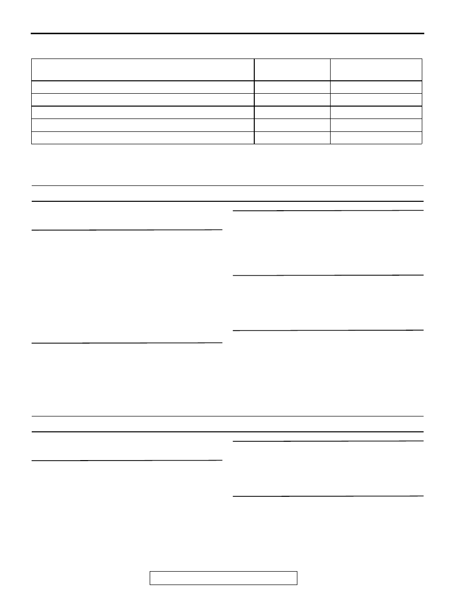
SYMPTOM CHART
M1332009400290
SYMPTOM PROCEDURES
INSPECTION PROCEDURE 1: Steering Wheel is Heavy, Vibrates or Pulls to One Side
DIAGNOSIS
STEP 1. Check the tires.
Check for the tire pressure, the tire pressure balance
between left and right tires, and the tire condition.
Refer to GROUP 31, Diagnosis
Q: Are the tires in normal condition?
YES :
Go to Step 2.
NO :
If out of pressure, adjust the tire pressure. If
out of balance, balance the tires as
necessary. If excessively worn, replace the
tires as necessary and then go to Step 5.
STEP 2. Check the wheel alignment.
Refer to
Q: Is the wheel alignment correct?
YES :
Go to Step 3.
NO :
Adjust it, and then go to Step 5.
STEP 3. Check the lower arm ball joint.
Q: Is the ball joint in good condition?
YES :
Go to Step 4.
NO :
Replace the lower arm assembly, and then
go to Step 5.
STEP 4. Check the coil spring.
Q: Is the coil spring in good condition?
YES :
Go to Step 5.
NO :
Replace it, and then go to Step 5.
STEP 5. Retest the system.
Q: Is the malfunction eliminated?
YES :
The procedure is complete.
NO :
Return to Step 1.
INSPECTION PROCEDURE 2: Excessive Body Rolling
DIAGNOSIS
STEP 1. Check for broken or deteriorated
stabilizer bar.
Q: Is the stabilizer bar in good condition?
YES :
Go to Step 2.
NO :
Replace it, and then go to Step 3.
STEP 2. Check the strut assembly for damage.
Q: Is the strut assembly in good condition?
YES :
Go to Step 3.
NO :
Replace it, and then go to Step 3.
STEP 3. Retest the system.
Q: Is the malfunction eliminated?
YES :
The procedure is complete.
NO :
Return to Step 1.
SYMPTOM
INSPECTION
PROCEDURE
REFERENCE PAGE
Steering wheel is heavy, vibrates or pulls to one side
1
Excessive body rolling
2
Poor ride
3
Unequal ride height
4
Noise
5