Mitsubishi Galant (2004+). Manual - part 1379


  Index      Mitsubishi     Mitsubishi Galant - service repair manual 2004 year


Search            


Content   ..  1377  1378  1379  1380   ..


Mitsubishi Galant (2004+). Manual - part 1379


CROSSMEMBER

TSB Revision

POWER PLANT MOUNT

32-15

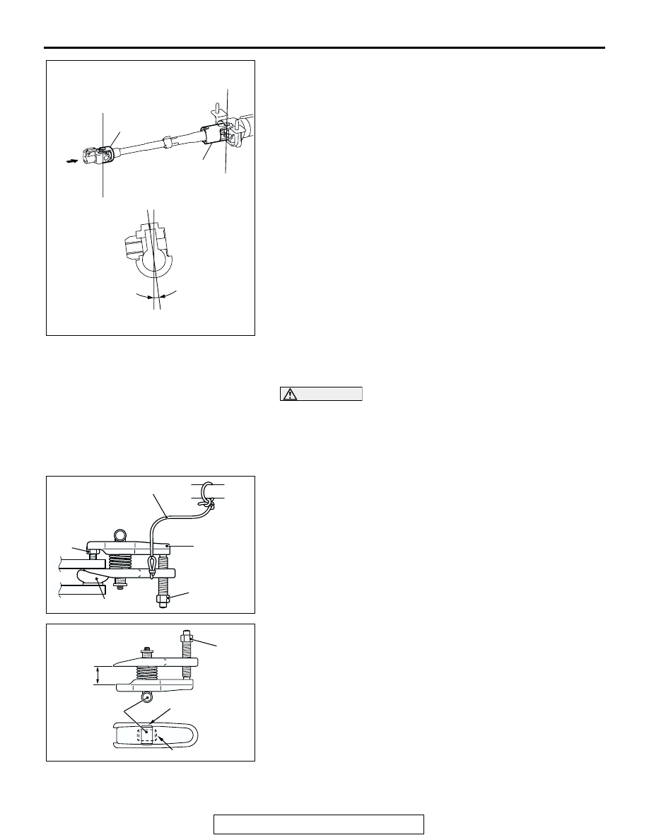
NOTE: If the steering column shaft is removed accidentally, 
remove the steering column assembly and be sure to insert the 
steering column shaft into the steering column as shown in the 
figure. 

.

<<B>> SELF LOCKING NUTS (CONNECTION FOR TIE ROD 
END AND LOWER ARM BALL JOINT) REMOVAL

CAUTION

• Do not remove the nut from ball joint. Loosen it and use 

special tool MB991897 to avoid possible damage to ball 
joint threads.

• Hang special tool MB991897 with a cord to prevent it 

from falling. 

1. Replace the self locking nut for lower arm ball joint with a 

regular nut, because the original one is a little bit large to 
install special tool MB991897. Install special tool MB991897 
as shown in the figure.

2. Turn the bolt and knob as necessary to make the jaws of 

special tool parallel, tighten the bolt by hand and confirm 
that the jaws are still parallel.
NOTE: When adjusting the jaws in parallel, make sure the 
knob is in the position shown in the figure.

3. Tighten the bolt with a wrench to disconnect the lower arm 

ball joint, tie rod end and remove the self locking nut.

.

AC306564 AB

X

X

Y

Y

X

X

Y

Y

YOKE Y

VIEW A

7.6˚ ± 3˚

YOKE X

A

AC208247AC

CORD

BOLT

MB991897

NUT

BALL JOINT

AC106821

KNOB

PARALLEL

BOLT

CORRECT

WRONG

AC

CROSSMEMBER

TSB Revision

POWER PLANT MOUNT

32-16

<<C>> FRONT AXLE CROSSMEMBER STOPPER 
REMOVAL
The crossmember mounting bolts need not be unscrewed 
when the front axle crossmember stopper is replaced. How-
ever, the bolts may become loosened when the front axle 
crossmember stopper is removed. Retighten the bolts to 180 

± 

20 N

⋅m (133 ± 15 ft-lb).

.

<<D>> FRONT AXLE CROSSMEMBER STAY REMOVAL
The crossmember mounting bolts need not be unscrewed 
when the front axle crossmember stay is replaced. However, 
the bolts may become loosened when the front axle crossmem-
ber stay is removed. Retighten the bolts to 180 

± 20 N⋅m (133 ± 

15 ft-lb).

.

<<E>> ENGINE REAR ROLL STOPPER BRACKET, POWER 
STEERING GEAR AND LINKAGE, STABILIZER BAR AND 
FRONT AXLE NO.1 CROSSMEMBER ASSEMBLY 
REMOVAL
Support the front axle number 1 crossmember with a transmis-
sion jack, and then remove the crossmember mounting nuts 
and bolts.

AC307551AB

FRONT AXLE 
CROSSMEMBER 
STOPPER

CROSSMEMBER 
MOUNTING BOLT

AC306568 AB

FRONT AXLE 
CROSSMEMBER 
STAY

CROSSMEMBER 
MOUNTING BOLT

AC206593

AC306696

TRANSMISSION
JACK

AB

CROSSMEMBER

TSB Revision

POWER PLANT MOUNT

32-17

INSTALLATION SERVICE POINTS

.

>>A<< STABILIZER BAR INSTALLATION
Align the stabilizer bar identification mark with the right end of 
the bushing (LH).

.

>>B<< POWER STEERING GEAR BRACKET/ENGINE 
REAR ROLL STOPPER BRACKET INSTALLATION
Tighten the bolts in the following sequence:
1. Tighten bolt A and then tighten bolt B.
2. Tighten bolts E finger tight.
3. Tighten bolt C and then tighten bolts D.
4. Tighten bolts E and then tighten bolt F.

.

>>C<< ENGINE REAR ROLL STOPPER BRACKET, POWER 
STEERING GEAR AND LINKAGE, STABILIZER BAR AND 
FRONT AXLE NO.1 CROSSMEMBER ASSEMBLY 
INSTALLATION
Align the steering column dash panel cover notch (arrow A) 
with the steering gear lug (arrow B), and install the engine rear 
roll stopper bracket, power steering gear and linkage, stabilizer 
bar and front axle number 1 crossmember assembly.

.

AC006141AE

STABILIZER 
BRACKET (LH)

OUTSIDE OF
VEHICLE

STABILIZER 
BUSHING (LH)

APPROXIMATELY 
20 mm ( 0.79 in )

IDENTIFICATION
MARK

AC306791AB

A

C

B

D

FRONT OF VEHICLE

D

E

E

F

AC306751 AB

B

A

STEERING GEAR

STEERING COLUMN 
DASH PANEL COVER

CROSSMEMBER

TSB Revision

POWER PLANT MOUNT

32-18

>>D<< FRONT AXLE CROSSMEMBER 
STAY/SELF-LOCKING NUTS INSTALLATION
Ensure that the crossmember mounting bolts have been tight-
ened to 180 

± 20 N⋅m (133 ± 15 ft-lb), and then install the front 

crossmember stay with the self-locking nut.

.

>>E<< FRONT AXLE CROSSMEMBER 
STOPPER/SELF-LOCKING NUTS INSTALLATION
Ensure that the crossmember mounting bolts have been tight-
ened to 180 

± 20 N⋅m (133 ± 15 ft-lb), and then install the front 

crossmember stopper with the self-locking nut.

INSPECTION

M1321003300194

• Check the crossmembers for cracks or damage.

AC306568 AC

FRONT AXLE 
CROSSMEMBER 
STAY

CROSSMEMBER 
MOUNTING BOLT

SELF-LOCKING NUT

AC307551AC

FRONT AXLE 
CROSSMEMBER 
STOPPER

CROSSMEMBER 
MOUNTING BOLT

SELF-LOCKING NUT


Content   ..  1377  1378  1379  1380   ..