Content .. 1375 1376 1377 1378 ..
Mitsubishi Galant (2004+). Manual - part 1377
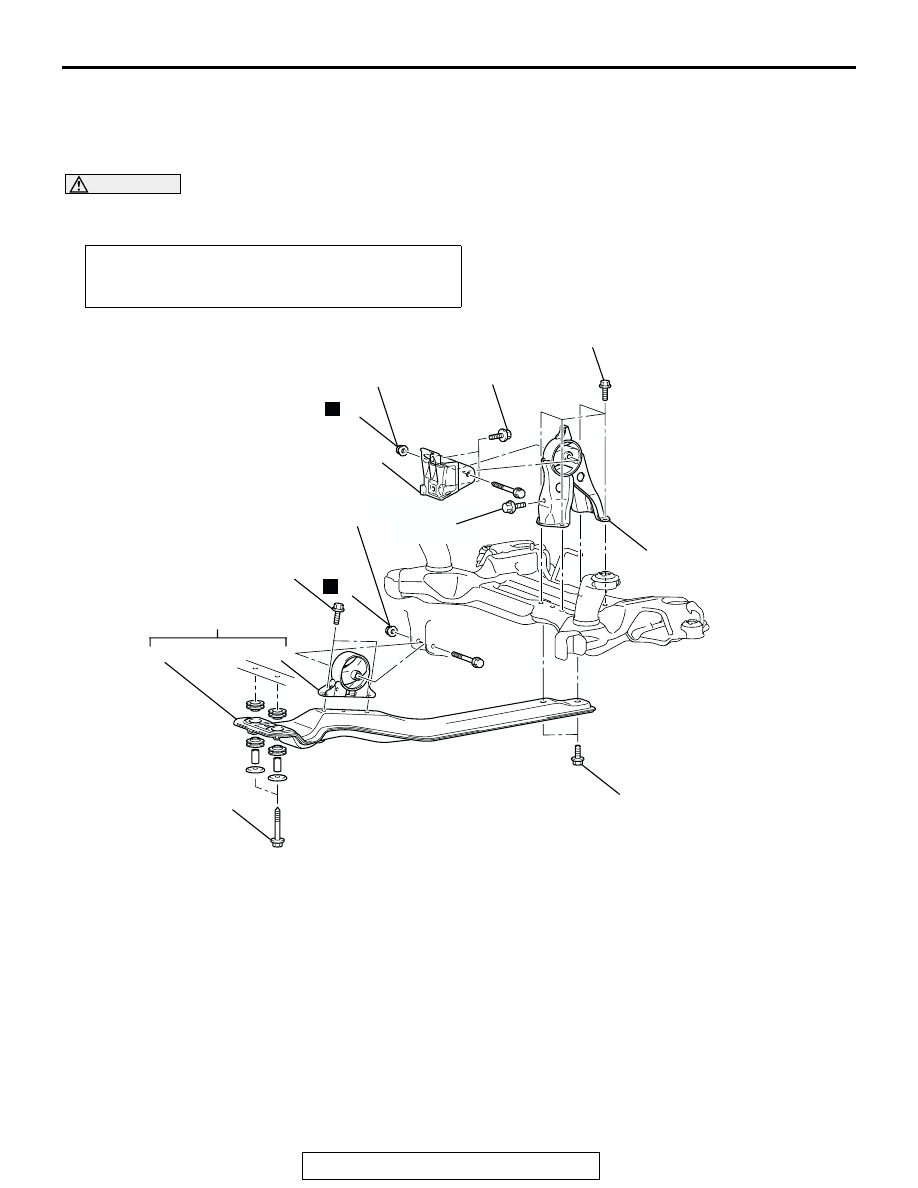
ENGINE ROLL STOPPER AND CENTERMEMBER
TSB Revision
POWER PLANT MOUNT
32-7
ENGINE ROLL STOPPER AND CENTERMEMBER
REMOVAL AND INSTALLATION
M1321002300306
<2.4L ENGINE>
CAUTION
*: Indicates parts which should be initially tightened, and then fully tightened after placing the vehicle
horizontally and loading the full weight of the engine on the vehicle body.
Pre-removal and Post-installation Operation
Side Under Cover Removal and Installation (Refer to
GROUP 51, Under Cover
AC306905
1
7
6
5
4
3
2
83 ± 12 N·m
61 ± 9 ft-lb
83 ± 12 N·m
61 ± 9 ft-lb
58 ± 7 N·m*
43 ± 5 ft-lb*
58 ± 7 N·m*
43 ± 5 ft-lb*
58 ± 7 N·m*
43 ± 5 ft-lb*
90 ± 10 N·m
67 ± 7 ft -lb
58 ± 7 N·m*
43 ± 5 ft-lb*
AB
58 ± 7 N·m
43 ± 5 ft-lb
N
N
FRONT ROLL STOPPER AND
CENTERMEMBER REMOVAL
STEPS
1.
SELF-LOCKING NUT
2.
ENGINE FRONT ROLL STOPPER
BRACKET AND
CENTERMEMBER
>>B<<
3.
ENGINE FRONT ROLL STOPPER
BRACKET
4.
CENTERMEMBER
REAR ROLL STOPPER
REMOVAL STEPS
•
FRONT AXLE NO.1
CROSSMEMBER ASSEMBLY
(REFER TO
>>A<<
5.
ENGINE REAR ROLL STOPPER
BRACKET