Mitsubishi Galant (2004+). Manual - part 137


  Index      Mitsubishi     Mitsubishi Galant - service repair manual 2004 year


Search            


Content   ..  135  136  137  138   ..


Mitsubishi Galant (2004+). Manual - part 137


ENGINE ASSEMBLY

TSB Revision

ENGINE MECHANICAL <2.4L ENGINE>

11A-21

REMOVAL SERVICE POINTS

.

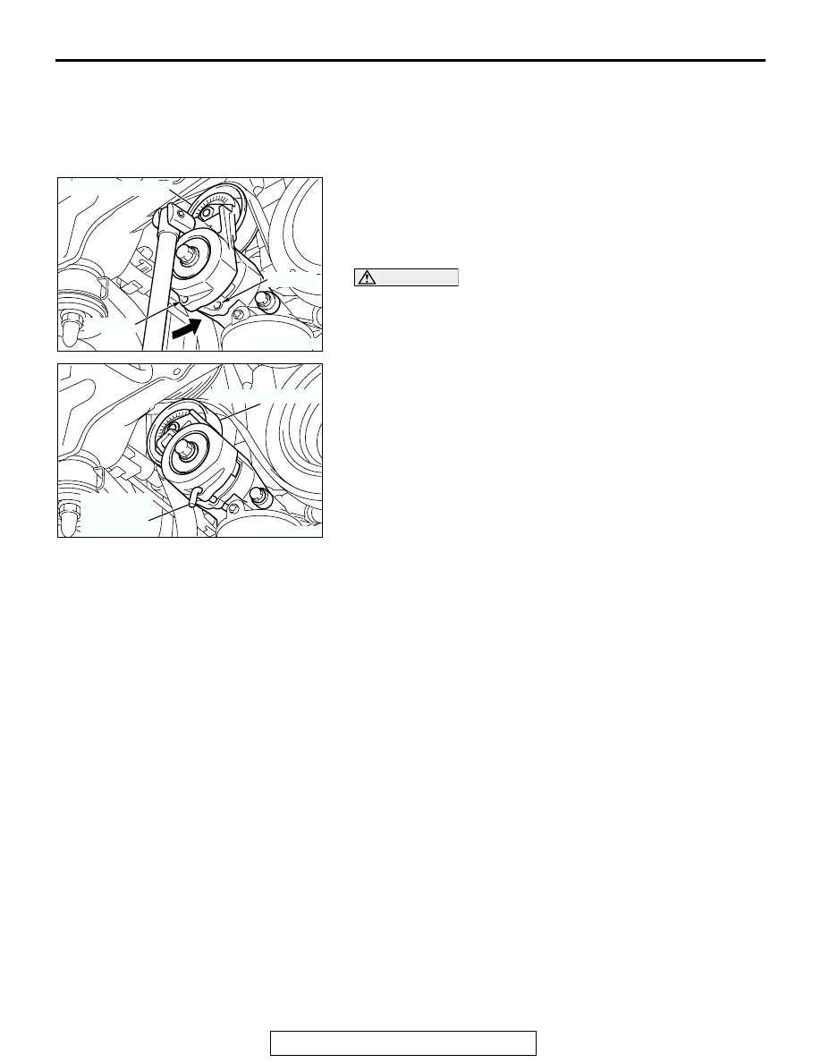
<<A>> DRIVE BELT REMOVAL
The following operations will be needed due to the introduction 
of the serpentine drive system with the drive belt auto-ten-
sioner.
1. Securely insert the spindle handle or ratchet handle with a 

12.7 mm (1/2-inch) insertion angle into the jig hole of the 
auto-tensioner. 

2. Rotate the auto-tensioner counterclockwise and align hole A 

with hole B.

CAUTION

To reuse the drive belt, draw an arrow indicating the rotat-
ing direction (clockwise) on the back of the belt using 
chalk, etc.

3. Insert an L-shaped hexagon wrench, etc. into the hole to fix 

and then remove the drive belt.

.

<<B>> POWER STEERING OIL PUMP AND BRACKET 
ASSEMBLY REMOVAL
With the hose installed, remove the power steering oil pump 
and bracket assembly from the engine assembly.
NOTE: After removing the power steering oil pump and bracket 
assembly, secure it with a cord in the location where the 
removal and installation of the engine assembly cannot be hin-
dered. 

.

<<C>> A/C COMPRESSOR AND CLUTCH ASSEMBLY 
REMOVAL
With the hose installed, remove the A/C compressor and clutch 
assembly from the bracket.
NOTE: After removing the A/C compressor and clutch assem-
bly, secure it with a cord in the location where the removal and 
installation of the engine assembly cannot be hindered. 

.

<<D>> ATF WARMER (TRANSMISSION FLUID COOLER) 
AND BRACKET ASSEMBLY REMOVAL
With the hose installed, remove the ATF warmer (transmission 
fluid cooler) &bracket assembly from the transmission case 
front roll stopper bracket.

.

AC301703

AC301704AB

AUTO-TENSIONER

HOLE B

HOLE A

AC301705AB

AUTO-TENSIONER

L-SHAPED
HEXAGON
WRENCH

ENGINE ASSEMBLY

TSB Revision

ENGINE MECHANICAL <2.4L ENGINE>

11A-22

<<E>> FUEL HIGH-PRESSURE HOSE REMOVAL
1. Remove the fuel high-pressure hose stopper.

2. Remove the fuel high-pressure hose in the direction shown 

in the figure while the retainer is pulled up. 
NOTE: If the retainer is released, install it after removing the 
fuel high-pressure hose.

.

<<F>> TRANSAXLE ASSEMBLY REMOVAL
1. Frame front end structure bar provisorily.

NOTE: Secure A/C condenser and front end structure bar 
with a cord in the location where the removal and installation 
of the engine assembly cannot be hindered.

2. Remove the transaxle assembly. (Refer to GROUP 23A, 

Transaxle Assembly 

P.23A-392

).

.

<<G>> POWER STEERING OIL RESERVOIR REMOVAL
With the hose installed, remove the power steering oil reservoir 
from the vehicle. (Refer to GROUP 37A, Power Steering Hoses 

P.37A-57

).

NOTE: After removing the power steering oil reservoir, secure it 
with a cord in the location where the removal and installation of 
the engine front mounting bracket cannot be hindered. 

.

<<H>> ENGINE FRONT MOUNTING BRACKET REMOVAL
1. Support the engine with a garage jack.
2. Remove the following special tool.

AC304581

AB

STOPPER

AC304582

AB

RETAINER 

AC307148

AB

FRONT END 
STRUCTURE BAR

ENGINE ASSEMBLY

TSB Revision

ENGINE MECHANICAL <2.4L ENGINE>

11A-23

(1) <Special tool MB991895 is used>

Remove special tool MB991895.

(2) <Special tool MB991928 is used>

Remove special tool MB991928.

3. Hold the engine assembly with a chain block, etc.
4. Place a garage jack against the engine oil pan with a piece 

of wood in between so that the weight of the engine 
assembly is no longer being applied to the engine front 
mounting bracket.

5. Loosen the engine front mounting bracket mounting nuts 

and bolts, and remove the engine front mounting bracket.

.

<<I>> ENGINE ASSEMBLY REMOVAL
After checking that all cables, hoses and wiring harness con-
nectors and so on are disconnected from the engine, lift the 
chain block slowly to remove the engine assembly upward from 
the engine compartment.

INSTALLATION SERVICE POINTS

.

>>A<< ENGINE ASSEMBLY INSTALLATION
Install the engine assembly, being careful not to pinch the 
cables, hoses or wiring harness connectors.

.

AC306198

MB991527

MB991454

MB991895

AB

AC306200

AB

MB991928

MB991527

MB991454

AC306753AB

MB991527

MB991454

AC306753AB

MB991527

MB991454

ENGINE ASSEMBLY

TSB Revision

ENGINE MECHANICAL <2.4L ENGINE>

11A-24

>>B<< ENGINE FRONT MOUNTING BRACKET 
INSTALLATION
1. Place a garage jack against the engine oil pan with a piece 

of wood in between, and install the engine front mounting 
bracket while adjusting the position of the engine.

2. Support the engine assembly with a garage jack.
3. Remove the chain block.
4. Use the following special tool as during removal to support 

the engine.

(1) <Special tool MB991895 is used>

Set special tool MB991895. (Refer to GROUP 23A, 
Transaxle Assembly 

P.23A-392

).

(2) <Special tool MB991928 is used>

Set special tool MB991928. (Refer to GROUP 23A, 
Transaxle Assembly 

P.23A-392

).

.

>>C<<TRANSAXLE ASSEMBLY INSTALLATION
1. Install the transaxle assembly. (Refer to GROUP 23A, 

Transaxle Assembly 

P.23A-392

).

2. Remove the front end structure bar.

.

AC306198

MB991527

MB991454

MB991895

AB

AC306200

AB

MB991928

MB991527

MB991454

AC307148

AB

FRONT END 
STRUCTURE BAR


Content   ..  135  136  137  138   ..