Mitsubishi Galant (2004+). Manual - part 1015


  Index      Mitsubishi     Mitsubishi Galant - service repair manual 2004 year


Search            


Content   ..  1013  1014  1015  1016   ..


Mitsubishi Galant (2004+). Manual - part 1015


MULTIPORT FUEL INJECTION (MFI) DIAGNOSIS

TSB Revision

MULTIPORT FUEL INJECTION (MFI) <2.4L ENGINE>

13A-877

Check Conditions

• Ignition switch is "ON" position.

Judgement Criteria

• Accelerator pedal position sensor (main) output 

voltage should be 4.8 volts or higher for 0.3 sec-
ond.

.

OBD-II DRIVE CYCLE PATTERN
None.

.

TROUBLESHOOTING HINTS (The most likely 
causes for this code to be set are:)

• Accelerator pedal position sensor failed.

• Open accelerator pedal position sensor (main) 

circuit, harness damage or connector damage.

• PCM failed.

DIAGNOSIS

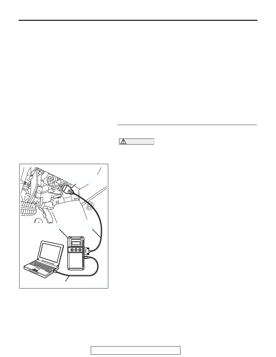
Required Special Tools:

• MB991958: Scan tool (MUT-III Sub Assembly)

• MB991824: V.C.I.

• MB991827: USB Cable

• MB991910: Main Harness A

STEP 1. Using scan tool MB991958, check data list item 78: 
Accelerator Pedal Position Sensor (main).

CAUTION

To prevent damage to scan tool MB991958, always turn the 
ignition switch to the "LOCK"(OFF) position before con-
necting or disconnecting scan tool MB991958.
(1) Connect scan tool MB991958 to the data link connector.
(2) Turn the ignition switch to the "ON" position.
(3) Set scan tool MB991958 to the data reading mode for item 

78, Accelerator Pedal Position Sensor (main).

• Output voltage is between 0.7 and 1.3 volts when foot is 

released from accelerator pedal.

• Output voltage is 4.0 volts or higher when accelerator 

pedal is fully depressed.

(4) Turn the ignition switch to the "LOCK"(OFF) position.
Q: Is the sensor operating properly?

YES : It can be assumed that this malfunction is intermittent. 

Refer to GROUP 00, How to Use 
Troubleshooting/Inspection. Service Points 

P.00-6

.

NO :  Go to Step 2.

AK303804AB

MB991910

DATA LINK
CONNECTOR

MB991824

MB991827

MULTIPORT FUEL INJECTION (MFI) DIAGNOSIS

TSB Revision

MULTIPORT FUEL INJECTION (MFI) <2.4L ENGINE>

13A-878

STEP 2. Check harness connector C-24 at accelerator 
pedal position sensor for damage.

Q: Is the harness connector in good condition?

YES : Go to Step 3.
NO :  Repair or replace it. Refer to GROUP 00E, Harness 

Connector Inspection 

P.00E-2

. Then go to Step 8.

STEP 3. Check the continuity at accelerator pedal position 
sensor harness side connector C-24.

(1) Disconnect the connector C-24 and measure at the harness 

side.

(2) Measure the continuity between terminal No. 2 and ground.

• Should be less than 2 ohms.

Q: Does continuity exist?

YES : Go to Step 6.
NO :  Go to Step 4.

AK303906

1

6 5 4 3 2

AB

C-24 (B)

CONNECTOR: C-24

HARNESS CONNECTOR:
COMPONENT SIDE

AK303906

1

6 5 4 3 2

AB

C-24 (B)

CONNECTOR: C-24

HARNESS CONNECTOR:
COMPONENT SIDE

1

6 5 4 3 2

AK203017

C-24 HARNESS 
CONNECTOR: 
COMPONENT SIDE

AC

MULTIPORT FUEL INJECTION (MFI) DIAGNOSIS

TSB Revision

MULTIPORT FUEL INJECTION (MFI) <2.4L ENGINE>

13A-879

STEP 4. Check harness connector B-20 at PCM for 
damage.

Q: Is the harness connector in good condition?

YES : Go to Step 5.
NO :  Repair or replace it. Refer to GROUP 00E, Harness 

Connector Inspection 

P.00E-2

. Then go to Step 8.

AK303092

25

21

24 23 22

29 28 27 26

34 33 32 31 30

38 37 36 35

43 42 41 40 39

CONNECTOR: B-20

B-20

PCM

AB

HARNESS CONNECTOR: 
COMPONENT SIDE

AIR CLEANER

MULTIPORT FUEL INJECTION (MFI) DIAGNOSIS

TSB Revision

MULTIPORT FUEL INJECTION (MFI) <2.4L ENGINE>

13A-880

STEP 5. Check for open circuit and harness damage 
between accelerator pedal position sensor connector C-24 
(terminal No. 2) and PCM connector B-20 (terminal No. 31).

Q: Is the harness wire in good condition?

YES : Go to Step 7.
NO :  Repair it. Then go to Step 8.

STEP 6. Replace the accelerator pedal position sensor.

(1) Replace the accelerator pedal position sensor.
(2) Turn the ignition switch to the "ON" position.

(3) After the DTC has been deleted, read the DTC again.
(4) Turn the ignition switch to the "LOCK" (OFF) position.
Q: Is DTC P2123 set?

YES : Replace the PCM. Then go to Step 8.
NO :  The procedure is complete.

AK303906

1

6 5 4 3 2

AB

C-24 (B)

CONNECTOR: C-24

HARNESS CONNECTOR:
COMPONENT SIDE

AK303092

25

21

24 23 22

29 28 27 26

34 33 32 31 30

38 37 36 35

43 42 41 40 39

CONNECTOR: B-20

B-20

PCM

AB

HARNESS CONNECTOR: 
COMPONENT SIDE

AIR CLEANER

AK303906

1

6 5 4 3 2

AB

C-24 (B)

CONNECTOR: C-24

HARNESS CONNECTOR:
COMPONENT SIDE


Content   ..  1013  1014  1015  1016   ..