Mitsubishi Galant (2004+). Manual - part 1013


  Index      Mitsubishi     Mitsubishi Galant - service repair manual 2004 year


Search            


Content   ..  1011  1012  1013  1014   ..


Mitsubishi Galant (2004+). Manual - part 1013


MULTIPORT FUEL INJECTION (MFI) DIAGNOSIS

TSB Revision

MULTIPORT FUEL INJECTION (MFI) <2.4L ENGINE>

13A-869

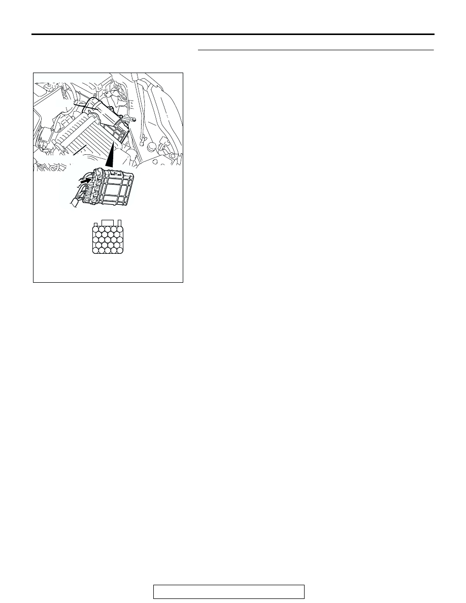
STEP 4. Check harness connector B-20 at PCM for 
damage.

Q: Is the harness connector in good condition?

YES : Go to Step 5.
NO :  Repair or replace it. Refer to GROUP 00E, Harness 

Connector Inspection 

P.00E-2

. Then go to Step 11.

AK303092

25

21

24 23 22

29 28 27 26

34 33 32 31 30

38 37 36 35

43 42 41 40 39

CONNECTOR: B-20

B-20

PCM

AB

HARNESS CONNECTOR: 
COMPONENT SIDE

AIR CLEANER

MULTIPORT FUEL INJECTION (MFI) DIAGNOSIS

TSB Revision

MULTIPORT FUEL INJECTION (MFI) <2.4L ENGINE>

13A-870

STEP 5. Check for open circuit and short circuit to ground 
between accelerator pedal position sensor connector C-24 
(terminal No. 1) and PCM connector B-20 (terminal No. 30).

Q: Is the harness wire in good condition?

YES : Go to Step 6.
NO :  Repair it. Then go to Step 11.

AK303906

1

6 5 4 3 2

AB

C-24 (B)

CONNECTOR: C-24

HARNESS CONNECTOR:
COMPONENT SIDE

AK303092

25

21

24 23 22

29 28 27 26

34 33 32 31 30

38 37 36 35

43 42 41 40 39

CONNECTOR: B-20

B-20

PCM

AB

HARNESS CONNECTOR: 
COMPONENT SIDE

AIR CLEANER

MULTIPORT FUEL INJECTION (MFI) DIAGNOSIS

TSB Revision

MULTIPORT FUEL INJECTION (MFI) <2.4L ENGINE>

13A-871

STEP 6. Using scan tool MB991958, check data list item 78: 
Accelerator Pedal Position Sensor (main).

CAUTION

To prevent damage to scan tool MB991958, always turn the 
ignition switch to the "LOCK"(OFF) position before con-
necting or disconnecting scan tool MB991958.
(1) Connect scan tool MB991958 to the data link connector.
(2) Turn the ignition switch to the "ON" position.
(3) Set scan tool MB991958 to the data reading mode for item 

78, Accelerator Pedal Position Sensor (main).

• Output voltage is between 0.7 and 1.3 volts when foot is 

released from accelerator pedal.

• Output voltage is 4.0 volts or higher when accelerator 

pedal is fully depressed.

(4) Turn the ignition switch to the "LOCK"(OFF) position.
Q: Is the sensor operating properly?

YES : It can be assumed that this malfunction is intermittent. 

Refer to GROUP 00, How to Use 
Troubleshooting/Inspection. Service Points 

P.00-6

.

NO :  Replace the PCM. Then go to Step 11.

STEP 7. Check harness connector B-20 at PCM for 
damage.

Q: Is the harness connector in good condition?

YES : Go to Step 8.
NO :  Repair or replace it. Refer to GROUP 00E, Harness 

Connector Inspection 

P.00E-2

. Then go to Step 11.

AK303804AB

MB991910

DATA LINK
CONNECTOR

MB991824

MB991827

AK303092

25

21

24 23 22

29 28 27 26

34 33 32 31 30

38 37 36 35

43 42 41 40 39

CONNECTOR: B-20

B-20

PCM

AB

HARNESS CONNECTOR: 
COMPONENT SIDE

AIR CLEANER

MULTIPORT FUEL INJECTION (MFI) DIAGNOSIS

TSB Revision

MULTIPORT FUEL INJECTION (MFI) <2.4L ENGINE>

13A-872

STEP 8. Check for harness damage between accelerator 
pedal position sensor connector C-24 (terminal No. 1) and 
PCM connector B-20 (terminal No. 30).

Q: Is the harness wire in good condition?

YES : Go to Step 9.
NO :  Repair it. Then go to Step 11.

AK303906

1

6 5 4 3 2

AB

C-24 (B)

CONNECTOR: C-24

HARNESS CONNECTOR:
COMPONENT SIDE

AK303092

25

21

24 23 22

29 28 27 26

34 33 32 31 30

38 37 36 35

43 42 41 40 39

CONNECTOR: B-20

B-20

PCM

AB

HARNESS CONNECTOR: 
COMPONENT SIDE

AIR CLEANER


Content   ..  1011  1012  1013  1014   ..