Mitsubishi Galant. Manual - part 583


  Index      Mitsubishi     Mitsubishi Galant - service repair manual 2001 year


Search            


Content   ..  581  582  583  584   ..


Mitsubishi Galant. Manual - part 583


MARK

TSB Revision

EXTERIOR

51-17

2. Installation procedure

(1) Use 3M

 AAD Part number 8906 or equivalent to clean 

the mark installation surfaces on the body.

CAUTION

When attaching the marks, the surrounding temperature 
should be 20 

−−−−

 38

°°°°

C (60 

−−−−

 100

°°°°

F) and the air should be 

completely free from dust. If the surrounding temperature 
is low than 20

°°°°

C (60

°°°°

F

), 

), 

), 

), 

the marks and their application 

surface on the body should be heated to 20 

−−−−

 38

°°°°

C (60 

−−−−


100

°°°°

F). 

(2) Peel off the backing paper from the reverse side of the 

marks, and then attach the marks to the vehicle body so 
that they fit properly into position.

AC000648

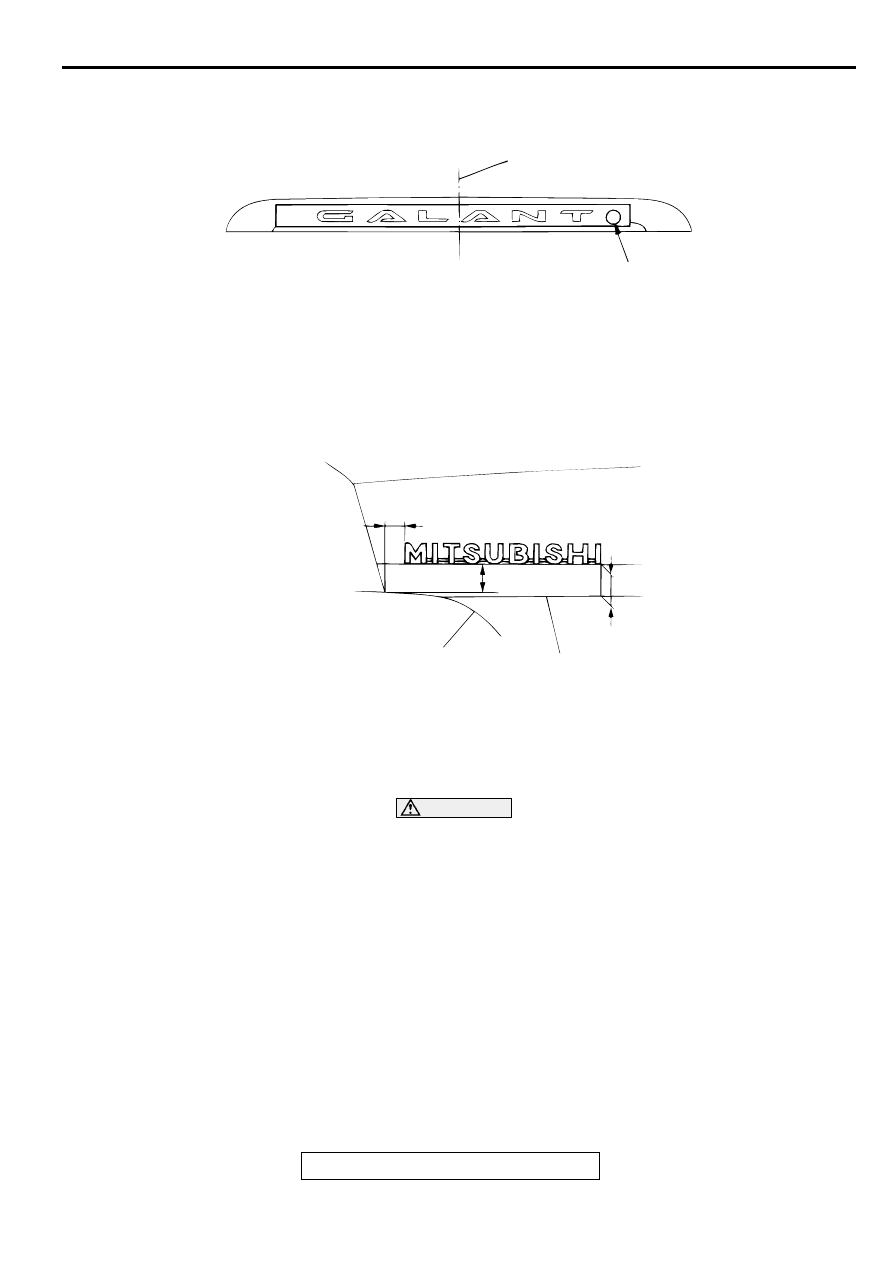
LICENSE LIGHT GARNISH CENTER LINE

ALIGN WITH LICENSE

LIGHT GARNISH HOLE

AB

"GALANT" MARK

AC003630AB

15.8 mm

(0.62 in)

24.2 mm (0.95 in)

27.3 mm

(1.07 in)

TRUNK LID

END LINE

TRUNK LID

PRESS LINE

"MITSUBISHI" MARK

DOOR MIRROR

TSB Revision

EXTERIOR

51-18

D O O R  M IR R O R

SPECIAL TOOL

M1511000600348

REMOVAL AND INSTALLATION

M1511006400074

Required Special Tool:

MB990784: Ornament Remover

TOOL

TOOL NUMBER AND 
NAME

REPLACED BY MILLER 
TOOL NUMBER

APPLICATION

MB990784 Ornament 
remover

General service tool

Removal of remote 
controlled mirror switch

MB990784

AC003580

1

3

5

7

8

9

4

5

6

7

8

9

2

3

5

8

9

 A

 B

 C

AB

1.

REMOTE CONTROLLED 
MIRROR SWITCH

DOOR MIRROR REMOVAL STEPS
2. LEVER KNOB
3. DELTA COVER, INNER
4. TWEETER COVER
5. DELTA COVER BASE
6. TWEETER

7. HARNESS CONNECTOR 

<VEHICLES WITH REMOTE 
CONTROLLED MIRROR>

8. DOOR MIRROR ASSEMBLY

<<A>>

9. MIRROR

DOOR MIRROR REMOVAL STEPS 

DOOR MIRROR

TSB Revision

EXTERIOR

51-19

REMOVAL SERVICE POINT

<<A>> MIRROR REMOVAL
Let the mirror face up, insert a flat-tipped screwdriver wound 
with masking tape, and remove the mirror by releasing the 
spring from the hook.

INSPECTION

M1511006500071

REMOTE CONTROLLED MIRROR ASSEMBLY 
CHECK
<Vehicles without heated mirror>

Check that the mirror moves as described in the table when 
each terminal is connected to the battery.

<Vehicles with heated mirror>

1. Check that the mirror moves as described in the table when 

each terminal is connected to the battery

2. Check if there is continuity between terminals (4) and (5).

AC003581AB

SPRING

HOOK

DIRECTION 
OPERATION

TESTER 
CONNECTION

SPECIFIED 
CONDITION

Up

1-Battery(+), 3-
Battery(-)

Continuity

Down

1-Battery(-), 3-
Battery(+)

Continuity

Left

2-Battery(-), 3-
Battery(+)

Continuity

Right

2-Battery(+), 3-
Battery(-)

Continuity

AC003582

DIRECTION 
OPERATION

TESTER 
CONNECTION

SPECIFIED 
CONDITION

Up

1-Battery(+), 3-
Battery(-)

Continuity

Down

1-Battery(-), 3-
Battery(+)

Continuity

Left

2-Battery(-), 3-
Battery(+)

Continuity

Right

2-Battery(+), 3-
Battery(-)

Continuity

AC003582

SPECIFICATIONS

TSB Revision

EXTERIOR

51-20

REMOTE CONTROLLED MIRROR SWITCH 
CONTINUITY CHECK

SPECIFIC ATIO NS

FASTENER TIGHTENING SPECIFICATIONS

M1511015300097

SERVICE SPECIFICATIONS

M1511000300080

 ADHESIVES

M1511000500095

SWITCH POSITION

TESTER 
CONNECTION

SPECIFIED 
CONDITION

Left side

Up

 8, 9 

 11

Continuity

Down

 9, 8 

 11

Continuity

Left

 9, 8 

 10

Continuity

Right

 8, 9 

 10

Continuity

Right side

Up

 9, 6 

 8

Continuity

Down

 9, 8 

 11

Continuity

Left

 9, 8 

 10

Continuity

Right

 8, 9 

 10

Continuity

AC003583

ITEMS

SPECIFICATIONS

Windshield wiper and washer

Wiper arm and blade assembly nut

13 N

m (115 in-lb)

Wiper link assembly bolt

5 N

m (44 in-lb)

Wiper motor bolt

9 N

m (80 in-lb)

ITEMS

STANDARD VALUE

Windshield wiper blade position 
installation mm (in)

Driver's side

20 

 30 (0.8 

 1.2)

Passenger's side

30 

 45 (1.2 

 1.8)

ITEM

SPECIFICATIONS

Door molding assembly, door garnish assembly.

Adhesive tape: Double-sided tape 
A; 10 mm (0.4 in) width and 0.8 mm (0.03 in) 
thickness
B, C; 0.8 mm (0.03 in) thickness
D; 5 mm (0.2 in) width and 0.8 mm (0.3 in) thickness


Content   ..  581  582  583  584   ..