Mitsubishi Galant. Manual - part 520


  Index      Mitsubishi     Mitsubishi Galant - service repair manual 2001 year


Search            


Content   ..  518  519  520  521   ..


Mitsubishi Galant. Manual - part 520


ANTI-SKID BRAKING SYSTEM (ABS) DIAGNOSIS

TSB Revision

ANTI-LOCK BRAKING SYSTEM(ABS)

35B-13

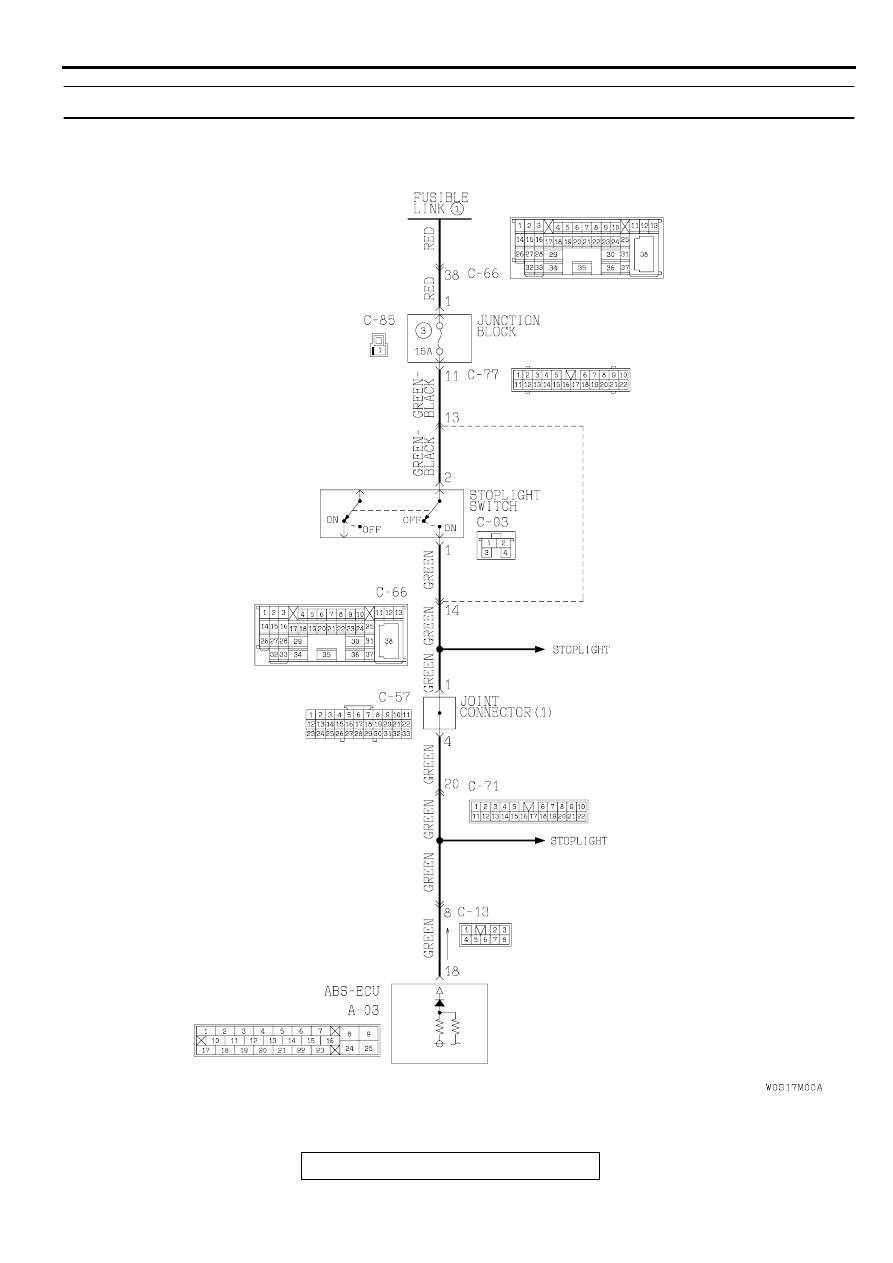
DTC 38 : Stoplight Switch System

AC003901AB

Stoplight Switch Circuit

ANTI-SKID BRAKING SYSTEM (ABS) DIAGNOSIS

TSB Revision

ANTI-LOCK BRAKING SYSTEM(ABS)

35B-14

CIRCUIT OPERATION

The ON signal when the brake pedal is pressed 
or the OFF signal when the brake pedal is 
released is input to the ABS-ECU (terminal 18).

ABS DTC SET CONDITION
Output is provided in the following cases:

Stoplight switch is not operating properly and 
remains in ON state for more than 15 minutes.

Stoplight switch system harness is damaged and 
no signal is input to ABS-ECU.

TROUBLESHOOTING HINTS
The most likely causes for DTC is to set are:

Malfunction of the stoplight switch

Damaged wiring harness and connector

Malfunction of the hydraulic unit (Integrated with 
ABS-ECU)

AC003695 AB

CONNECTOR: A-03

AC003858

GLOVE BOX

AB

CONNECTOR: C-13

AC003868 AB

CONNECTOR: C-85

JUNCTION BLOCK (REAR VIEW)

AC003869

JUNCTION BLOCK (RH)

CONNECTOR: C-71

AB

AC003902

CONNECTORS: C-03, C-57

AB

C-57

C-03

AC003871

JUNCTION BLOCK (FRONT VIEW)

CONNECTOR: C-77

AB

AC003870 AB

CONNECTOR: C-66

CONNECTOR
BLOCK (LH)

ANTI-SKID BRAKING SYSTEM (ABS) DIAGNOSIS

TSB Revision

ANTI-LOCK BRAKING SYSTEM(ABS)

35B-15

DIAGNOSIS

Required Special Tool:

MB991223: Harness Set

STEP 1. Check the stoplight operation.

Q: Does the stoplight light or go out correctly?

YES : Go to Step 3.
NO :  Go to Step 2.

STEP 2. Check the stoplight switch installation condition.

Q: Is the stoplight switch installed properly?

YES : Go to Step 4.
NO :  Repair it and then go to Step 7.

STEP 3. Check the stoplight switch circuit at ABS-ECU 
connector A-03.
(1) Disconnect connector A-03 and measure at the harness 

side.

(2) Turn the stoplight switch "ON".
(3) Measure the voltage between terminal 18 and ground.

Q: Is the battery positive voltage approximately 12 volts?

YES : Replace the hydraulic unit and then go to Step 7.
NO :  Go to Step 5.

STEP 4. Check the stoplight switch continuity.
(1) Remove the stoplight switch. (Refer to GROUP 35A, Brake 

Pedal

P.35A-30

.)

(2) Connect an ohmmeter to the stoplight switch terminals 1 

and 2, and check whether there is continuity when the 
plunger of the stoplight switch is pushed in and when it is 
released.

(3) The stoplight switch is in good condition if there is no 

continuity when the plunger is pushed in to a depth of within 
4 mm (0.2 inch) from the outer case edge surface, and if 
there is continuity when it is released.

Q: Is the stoplight switch damaged?

YES : Replace it and then go to Step 7.
NO :  Go to Step 6.

AC003905

A-03 (HARNESS SIDE)

AB

AC002295 AB

AC000943 AB

NO CONTINUITY
(OFF)

CONTINUITY
(ON)

4 mm (0.2 in)

ANTI-SKID BRAKING SYSTEM (ABS) DIAGNOSIS

TSB Revision

ANTI-LOCK BRAKING SYSTEM(ABS)

35B-16

STEP 5. Check the harness wire between ABS-ECU 
connector A-03 and stoplight switch connector C-66.
NOTE: After inspecting intermediate connector C-13, C-57 or 
C-71 inspect the wire. If intermediate connector C-13, C-71 is 
damaged, repair or replace it. Refer to GROUP 00E, Harness 
Connector Inspection

P.00E-2

. If the connector has been 

repaired or replaced, go to Step 7.

AC003858

GLOVE BOX

AB

CONNECTOR: C-13

AC003869

JUNCTION BLOCK (RH)

CONNECTOR: C-71

AB

AC003089AE

CONNECTOR: C-57


Content   ..  518  519  520  521   ..