Mitsubishi Galant. Manual - part 296


  Index      Mitsubishi     Mitsubishi Galant - service repair manual 2001 year


Search            


Content   ..  294  295  296  297   ..


Mitsubishi Galant. Manual - part 296


MULTIPORT FUEL INJECTION(MFI) DIAGNOSIS

TSB Revision

MULTIPORT FUEL INJECTION (MFI) <3.0L>

13B-409

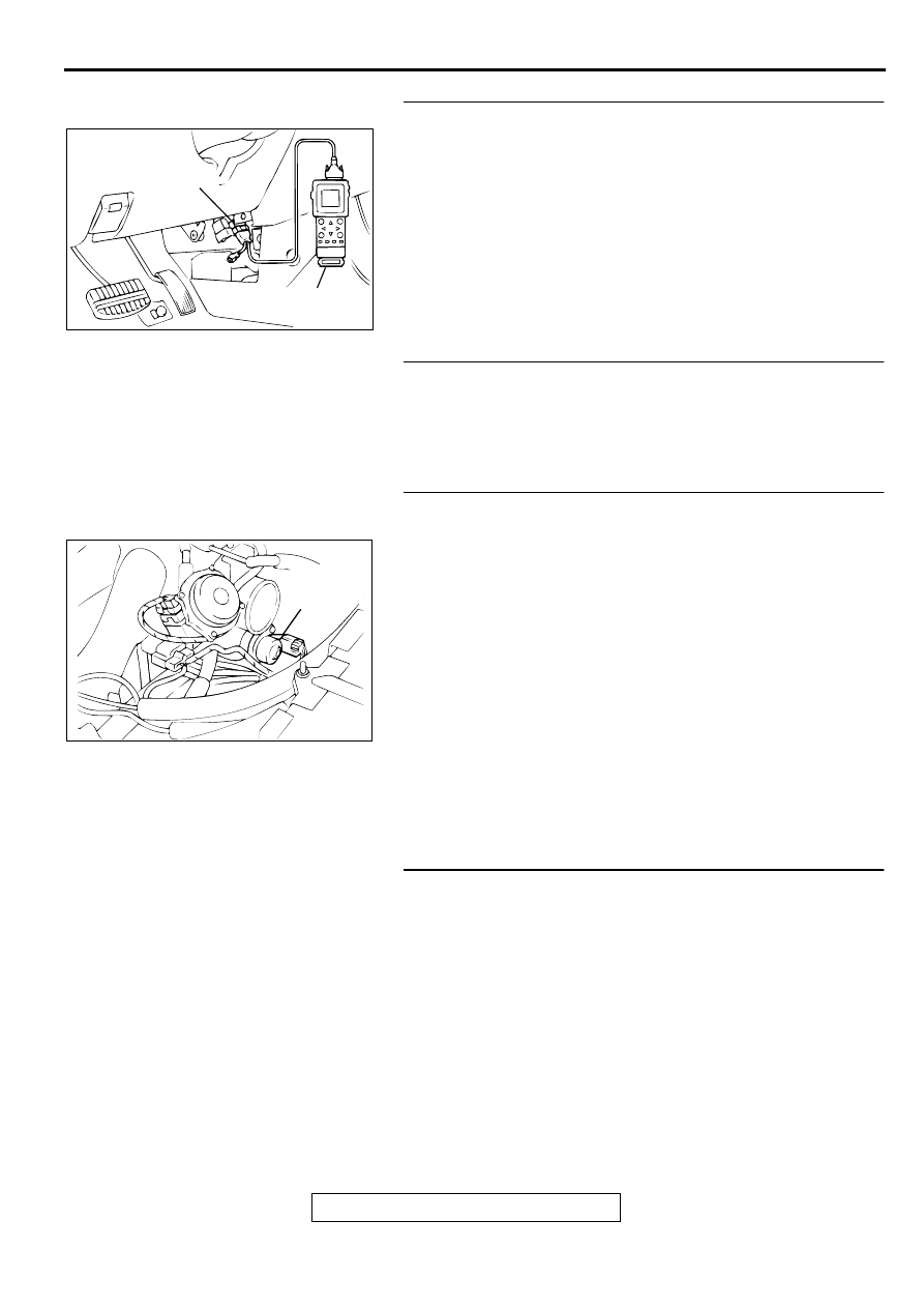
STEP 4. Using scan tool MB991502, check data list.
(1) Turn the ignition switch to the "ON" position.
(2) Check the following items in the data list. Refer to, Data List 

Reference Table(

P.13B-487

).

a. Item 21: Engine Coolant Temperature Sensor.

(3) Turn the ignition switch to the "LOCK" (OFF) position.

Q: Is the sensor operating properly?

YES : Go to Step 5.
NO :  Repair or replace. Then confirm that the malfunction 

symptom is eliminated.

STEP 5. Check the engine start-ability.
(1) Depress the accelerator pedal slightly, and start the engine.

Q: Is the start ability good?

YES : Go to Step 6.
NO :  Go to Step 7.

STEP 6. Check the idle air control (IAC) motor operation 
sound.
(1) Check that the engine coolant temperature is 20

°

 C (68

°

 F) 

or below.

NOTE: If necessary, you can disconnect the engine coolant 
temperature sensor connector and connect the harness 
side of the connector to another engine coolant temperature 
sensor that is at 20

° 

C(68

°

 F) or below.

(2) Check that the operation sound of the IAC motor can be 

heard after the ignition is switched to the "ON" position (but 
without starting the engine).

An operation sound is heard.

Q: Did you hear the operation sound?

YES : Refer to, Clean the throttle valve area(

P.13B-520

).

NO :  Refer to DTC P0506 Idle Control System RPM Lower 

Than Expected(

P.13B-338

), DTC P0507 Idle Control 

System RPM Higher Than Expected(

P.13B-347

).

STEP 7. Check the ignition timing.
(1) Check the ignition timing at cranking.

Standard value: 5

°°°°    

BTDC 

±±±±

 3

°°°°

Q: Is the ignition timing normal?

YES : Go to Step 8.
NO :  Check that the crankshaft position sensor and timing 

belt cover are in the correct position. Then confirm 
that the malfunction symptom is eliminated.

AC003081 AB

16 PIN

MB991502

ACX02523AG

IDLE AIR
CONTROL
MOTOR

MULTIPORT FUEL INJECTION(MFI) DIAGNOSIS

TSB Revision

MULTIPORT FUEL INJECTION (MFI) <3.0L>

13B-410

STEP 8. Check the left bank injector.
(1) Disconnect the left bank injector connector B-17, B-21, B-

30.

(2) Measure the resistance between each injector side 

connector terminals 1 and 2.

Standard value: 13 

−−−−

 16 ohm [at 20

°°°°    

C (68

°°°°

 F)]

Q: Is the resistance standard value?

YES : Go to Step 9.
NO :  Replace the faulty injector.Then confirm that the 

malfunction symptom is eliminated.

STEP 9. Check the right bank injector resistance at injector 
intermediate connector B-26.
(1) Disconnect the injector intermediate connector B-26.
(2) Measure the resistance between each male connector side 

terminal.

a. Measure the resistance between terminal 1 and 2 when 

measuring No.1 cylinder injector.

b. Measure the resistance between terminal 1 and 3 when 

measuring No.3 cylinder injector.

c. Measure the resistance between terminal 1 and 4 when 

measuring No.5 cylinder injector.

Resistance should be between 13 and 16 ohm [at 20

°


C(68

°

 F)].

Q: Is the resistance normal?

YES : Go to Step 12.
NO :  Go to Step 10.

AK000618 AD

CONNECTORS:B-17,B-21,B-30

B-30

B-17

B-21

AK000559

2

1

INJECTOR SIDE
CONNECTOR

AB

AK000618

AB

CONNECTOR:B-26

AK000447

1 2

3 4

INJECTOR
INTERMEDIATE
CONNECTOR

AB

MULTIPORT FUEL INJECTION(MFI) DIAGNOSIS

TSB Revision

MULTIPORT FUEL INJECTION (MFI) <3.0L>

13B-411

STEP 10. Check the right bank injector.
(1) Remove the intake manifold.
(2) Disconnect the right bank injector connector, which 

deviates from the standard value at Step 9.

(3) Measure the resistance between injector side connector 

terminals 1 and 2.

Standard value: 13 

−−−−

 16 ohm [at 20

°°°°    

C (68

°°°°

 F)]

Q: Is the resistance standard value?

YES : Go to Step 11.
NO :  Replace the injector.Then confirm that the malfunction 

symptom is eliminated.

STEP 11. Check connector B-19 or B-22 or B-25 at right 
bank injector for damage.
(1) Check the injector connector, which deviates from the 

standard value at Step 9.

Q: Is the connector in good condition?

YES : Repair harness wire between injector intermediate 

connector and right bank injector connector because 
of harness damage.Then confirm that the malfunction 
symptom is eliminated.

NO :  Repair or replace it.Refer to GROUP 00E, Harness 

Connector Inspection(

P.00E-2

).Then confirm that the 

malfunction symptom is eliminated.

STEP 12. Check connector B-26 at injector intermediate 
connector for damage.
Q: Is the connector in good condition?

YES : Go to Step 13.
NO :  Repair or replace it.Refer to GROUP 00E, Harness 

Connector Inspection(

P.00E-2

).Then confirm that the 

malfunction symptom is eliminated.

AK000618AC

CONNECTORS:B-19,B-22,B-25

B-25

B-19

B-22

AK000559

2

1

INJECTOR SIDE
CONNECTOR

AB

AK000618AC

CONNECTORS:B-19,B-22,B-25

B-25

B-19

B-22

AK000618

AB

CONNECTOR:B-26

MULTIPORT FUEL INJECTION(MFI) DIAGNOSIS

TSB Revision

MULTIPORT FUEL INJECTION (MFI) <3.0L>

13B-412

STEP 13. Check connector B-17, B-21, B-30 at left bank 
injector for damage.
Q: Is the connector in good condition?

YES : Go to Step 14.
NO :  Repair or replace it.Refer to GROUP 00E, Harness 

Connector Inspection(

P.00E-2

).Then confirm that the 

malfunction symptom is eliminated.

STEP 14. Check connector C-39 at PCM for damage.
Q: Is the connector in good condition?

YES : Go to Step 15.
NO :  Repair or replace it.Refer to GROUP 00E, Harness 

Connector Inspection(

P.00E-2

).Then confirm that the 

malfunction symptom is eliminated.

AK000618 AD

CONNECTORS:B-17,B-21,B-30

B-30

B-17

B-21

AK000280

CONNECTOR : C-39

PCM

AW


Content   ..  294  295  296  297   ..