Mitsubishi Galant. Manual - part 297


  Index      Mitsubishi     Mitsubishi Galant - service repair manual 2001 year


Search            


Content   ..  295  296  297  298   ..


Mitsubishi Galant. Manual - part 297


MULTIPORT FUEL INJECTION(MFI) DIAGNOSIS

TSB Revision

MULTIPORT FUEL INJECTION (MFI) <3.0L>

13B-413

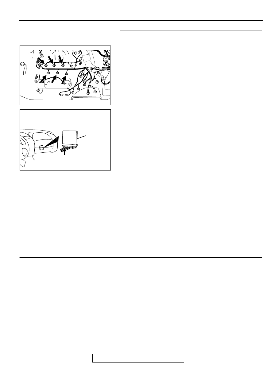
STEP 15. Check for harness damage between injector 
connector and PCM connector.

a. Check the harness wire between injector connector B-

22 terminal 2 and PCM connector C-39 terminal 1 when 
checking No.1 cylinder injector.

b. Check the harness wire between injector connector B-

21 terminal 2 and PCM connector C-39 terminal 9 when 
checking No.2 cylinder injector.

c. Check the harness wire between injector connector B-

19 terminal 2 and PCM connector C-39 terminal 24 
when checking No.3 cylinder injector.

d. Check the harness wire between injector connector B-

17 terminal 2 and PCM connector C-39 terminal 2 when 
checking No.4 cylinder injector.

e. Check the harness wire between injector connector B-

25 terminal 2 and PCM connector C-39 terminal 10 
when checking No.5 cylinder injector.

f. Check the harness wire between injector connector B-

30 terminal 2 and PCM connector C-39 terminal 25 
when checking No.6 cylinder injector.

Q: Is the harness wire in good condition?

YES : Check the following items, and repair or replace the 

defective items.

a. Check the ignition coil, spark plugs, spark plug 

cables.

b. Check if the injectors are clogged.

c. Check compression pressure.

d. Check fuel lines for clogging.
e. Check if the foreign materials (water, 

kerosene, etc.) got into fuel.

Then confirm that the malfunction symptom is 

eliminated.

NO :  Repair it.Then confirm that the malfunction symptom 

is eliminated.

INSPECTION PROCEDURE 7: Hard Starting

COMMENT

In cases such as the above, the cause is usually 
either weak spark, improper air-fuel mixture or 
low compression.

TROUBLESHOOTING HINTS (The most likely 
causes for this case:)

Malfunction of the ignition system.

Malfunction of the injector system.

Poor fuel quality. (Contamination)

Poor compression.

DIAGNOSIS

Required Special Tool:
MB991502: Scan Tool (MUT-II)

AK000618

AK000618 AE

CONNECTORS:B-17,B-19,B-21,B-22,B-25,B-30

B-25

B-19

B-22

B-30

B-17

B-21

AK000280

CONNECTOR : C-39

PCM

AW

MULTIPORT FUEL INJECTION(MFI) DIAGNOSIS

TSB Revision

MULTIPORT FUEL INJECTION (MFI) <3.0L>

13B-414

STEP 1. Check the battery positive voltage.
(1) Measure the battery positive voltage during cranking.

The voltage is 8 volts or more.

Q: Is the voltage normal?

YES : Go to Step 2.
NO :  Refer to GROUP 54A, Battery-Battery check(

P.54A-

5

).

STEP 2. Using scan tool MB991502, read the diagnostic 
trouble code (DTC).

CAUTION

To prevent damage to scan tool MB991502, always turn the 
ignition switch to the "LOCK" (OFF) position before 
connecting or disconnecting scan tool MB991502.
(1) Connect scan tool MB991502 to the data link connector.
(2) Turn the ignition switch to the "ON" position.
(3) Read the DTC.
(4) Turn the ignition switch to the "LOCK" (OFF) position.

Q: Is the DTC is output?

YES : Refer to Diagnostic Trouble Code Chart(

P.13B-19

). 

NO :  Go to Step 3.

STEP 3. Using scan tool MB991502, check actuator test.
(1) Turn the ignition switch to the "ON" position.
(2) Check the following items in the actuator test. Refer to 

Actuator Test Reference Table(

P.13B-499

).

a. Item 07: Fuel Pump.

(3) Turn the ignition switch to the "LOCK" (OFF) position.

Q: Is the actuator operating properly?

YES : Go to Step 4.
NO :  Repair or Replace. Then confirm that the malfunction 

symptom is eliminated.

STEP 4. Using scan tool MB991502, check data list.
(1) Turn the ignition switch the "ON" position.
(2) Check the following items in the data list. Refer to Data List 

Reference Table(

P.13B-487

).

a. Item 21: Engine Coolant Temperature Sensor.

(3) Turn the ignition switch to the "LOCK" (OFF) position.

Q: Is the sensor operating properly?

YES : Go to Step 5.
NO :  Repair or Replace. Then confirm that the malfunction 

symptom is eliminated.

AC003081 AB

16 PIN

MB991502

AC003081 AB

16 PIN

MB991502

AC003081 AB

16 PIN

MB991502

MULTIPORT FUEL INJECTION(MFI) DIAGNOSIS

TSB Revision

MULTIPORT FUEL INJECTION (MFI) <3.0L>

13B-415

STEP 5. Check the ignition timing.
(1) Check the ignition timing at cranking.

Standard value:5

°°°°    

BTDC 

±±±±

 3

°°°°

Q: Is the ignition timing normal?

YES : Go to Step 6.
NO :  Check that the crankshaft position sensor and timing 

belt cover are in the correct position. Then confirm 
that the malfunction symptom is eliminated.

STEP 6. Check the left bank injector.
(1) Disconnect the left bank injector connector B-17, B-21, B-

30.

(2) Measure the resistance between each injector side 

connector terminals 1 and 2.

Standard value: 13 

−−−−

 16 ohm [at 20

°°°°    

C (68

°°°°

 F)]

Q: Is the resistance standard value?

YES : Go to Step 7.
NO :  Replace the faulty injector. Then confirm that the 

malfunction symptom is eliminated.

AK000618 AD

CONNECTORS:B-17,B-21,B-30

B-30

B-17

B-21

AK000559

2

1

INJECTOR SIDE
CONNECTOR

AB

MULTIPORT FUEL INJECTION(MFI) DIAGNOSIS

TSB Revision

MULTIPORT FUEL INJECTION (MFI) <3.0L>

13B-416

STEP 7. Check the right bank injector resistance at injector 
intermediate connector B-26.
(1) Disconnect the injector intermediate connector B-26.
(2) Measure the resistance between each male connector side 

terminal.

a. Measure the resistance between terminal 1 and 2 when 

measuring No.1 cylinder injector.

b. Measure the resistance between terminal 1 and 3 when 

measuring No.3 cylinder injector.

c. Measure the resistance between terminal 1 and 4 when 

measuring No.5 cylinder injector.

Resistance should be between 13 and 16 ohm [at 20

°

 C 

(68

°

 F)].

Q: Is the resistance normal?

YES : Go to Step 10.
NO :  Go to Step 8.

STEP 8. Check the right bank injector.
(1) Remove the intake manifold.
(2) Disconnect the right bank injector connector, which 

deviates from the standard value at Step 7.

(3) Measure the resistance between injector side connector 

terminals 1 and 2.

Standard value: 13 

−−−−

 16 ohm [at 20

°°°°    

C (68

°°°°

 F)]

Q: Is the resistance standard value?

YES : Go to Step 9.
NO :  Replace the injector. Then confirm that the 

malfunction symptom is eliminated.

AK000618

AB

CONNECTOR:B-26

AK000447

1 2

3 4

INJECTOR
INTERMEDIATE
CONNECTOR

AB

AK000618AC

CONNECTORS:B-19,B-22,B-25

B-25

B-19

B-22

AK000559

2

1

INJECTOR SIDE
CONNECTOR

AB


Content   ..  295  296  297  298   ..