Mitsubishi Galant. Manual - part 252


  Index      Mitsubishi     Mitsubishi Galant - service repair manual 2001 year


Search            


Content   ..  250  251  252  253   ..


Mitsubishi Galant. Manual - part 252


MULTIPORT FUEL INJECTION(MFI) DIAGNOSIS

TSB Revision

MULTIPORT FUEL INJECTION (MFI) <3.0L>

13B-233

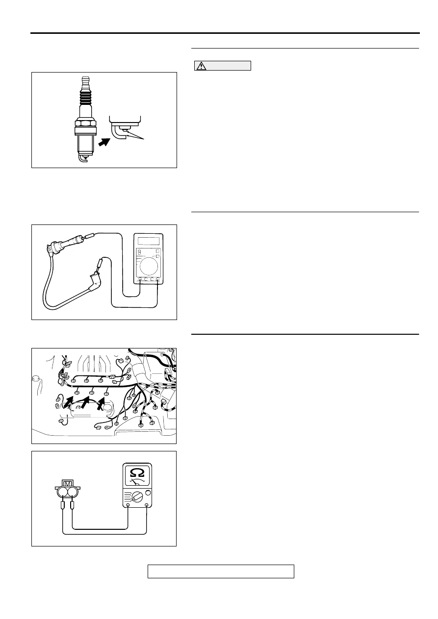
STEP 1. Check the spark plugs.

CAUTION

Do not attempt to adjust the gap of the platinum plug. 
Cleaning of the platinum plug may result in damage to the 
platinum tips. Therefore, if carbon deposits must be 
removed, use a plug cleaner and complete cleaning within 
20 seconds to protect the electrode. Do not use a wire 
brush.
(1) For the right bank cylinder, remove the intake manifold.
(2) Check the plug gap and replace if the limit is exceeded.

Standard value: 1.0 

−−−−

 1.1 mm (0.039 

−−−−

 0.043 inch)

Limit: 1.3 mm (0.051 inch)

Q: Is the plug gap at the standard value?

YES : Go to Step 2.
NO :  Replace the spark plug. Then go to Step 9.

STEP 2. Check the spark plug cable.
(1) Check the cap and coating for cracks.
(2) Measure the resistance.

Limit: maximum 22 k

Q: Is the resistance normal?

YES : Go to Step 3.
NO :  Replace the spark plug cable. Then go to Step 9.

STEP 3. Check the injector.
(1) Disconnect the injector connector B-22 <No.1 cylinder>, B-

21 <No.2 cylinder>, B-19 <No.3 cylinder>, B-17 <No.4 
cylinder>, B-25 <No.5 cylinder>, B-30 <No.6 cylinder>.

(2) Measure the resistance between injector side connector 

terminal 1 and 2.

Standard value: 13 

−−−−

 16 ohm [at 20

°°°°    

C (68

°°°°

 F )]

Q: Is the resistance standard value?

YES : Go to Step 4.
NO :  Replace the injector. Then go to Step 9.

AKX00383

AKX00383

Platinum
tips

AB

AKX00382

AK000618 AD

CONNECTORS:B-17,B-21,B-30

B-30

B-17

B-21

AK000559

2

1

INJECTOR SIDE
CONNECTOR

AB

MULTIPORT FUEL INJECTION(MFI) DIAGNOSIS

TSB Revision

MULTIPORT FUEL INJECTION (MFI) <3.0L>

13B-234

STEP 4. Check connector at injector and injector 
intermediate connector for damage.

a. Check the connector B-22 at injector and connector B-26 at 

injector intermediate connector when checking No.1 
cylinder.

b. Check the connector B-21 at injector and connector B-26 at 

injector intermediate connector when checking No.2 
cylinder.

c. Check the connector B-19 at injector and connector B-26 at 

injector intermediate connector when checking No.3 
cylinder.

d. Check the connector B-17 at injector and connector B-26 at 

injector intermediate connector when checking No.4 
cylinder.

e. Check the connector B-25 at injector and connector B-26 at 

injector intermediate connector when checking No.5 
cylinder.

f. Check the connector B-30 at injector and connector B-26 at 

injector intermediate connector when checking No.6 
cylinder.

Q: Is the connector in good condition?

YES : Go to Step 5.
NO :  Repair or replace the injector. Refer to GROUP 00E, 

Harness Connector Inspection (

P.00E-2

). Then go to 

Step 9.

STEP 5. Check connector C-39 at PCM for damage.
Q: Is the connector in good condition?

YES : Go to Step 6.
NO :  Repair or replace it. Refer to GROUP 00E, Harness 

Connector Inspection (

P.00E-2

). Then go to Step 9.

AK000618 AD

CONNECTORS:B-17,B-21,B-30

B-30

B-17

B-21

AK000618

AB

CONNECTOR:B-26

AK000280

CONNECTOR : C-39

PCM

AW

MULTIPORT FUEL INJECTION(MFI) DIAGNOSIS

TSB Revision

MULTIPORT FUEL INJECTION (MFI) <3.0L>

13B-235

STEP 6. Check for harness damage between injector 
connector and PCM connector.

a. Check the harness wire between injector connector B-22 

terminal 2 and PCM connector C-39 terminal 1 when 
checking No.1 cylinder.

b. Check the harness wire between injector connector B-21 

terminal 2 and PCM connector C-39 terminal 9 when 
checking No.2 cylinder.

c. Check the harness wire between injector connector B-19 

terminal 2 and PCM connector C-39 terminal 24 when 
checking No.3 cylinder.

d. Check the harness wire between injector connector B-17 

terminal 2 and PCM connector C-39 terminal 2 when 
checking No.4 cylinder.

e. Check the harness wire between injector connector B-25 

terminal 2 and PCM connector C-39 terminal 10 when 
checking No.5 cylinder.

f. Check the harness wire between injector connector B-30 

terminal 2 and PCM connector C-39 terminal 25 when 
checking No.6 cylinder.

Q: Is the harness wire in good condition?

YES : Go to Step 7.
NO :  Repair it. Then go to Step 9.

STEP 7. Check the compression.
Refer to GROUP 11C, On-Vehicle Service-Compression 
Pressure Check (

P.11C-7

).

Q: Are there any abnormalities?

YES : Go to Step 8.
NO :  Repair or replace it. Then go to Step 9.

STEP 8. Replace the injector.
(1) Replace the injector.
(2) Carry out a test drive with the drive cycle pattern. Refer to, 

Procedure 6 

 Other Monitor(

P.13B-4

).

(3) Check the diagnostic trouble code (DTC).

Q: Is the DTC P0301, P0302, P0303, P0304, P0305, P0306 is 

output?
YES : 
Replace the PCM. Then go to Step 9.
NO :  The inspection is complete.

AK000618 AD

CONNECTORS:B-17,B-21,B-30

B-30

B-17

B-21

AK000280

CONNECTOR : C-39

PCM

AW

AK000618 AD

CONNECTORS:B-17,B-21,B-30

B-30

B-17

B-21

MULTIPORT FUEL INJECTION(MFI) DIAGNOSIS

TSB Revision

MULTIPORT FUEL INJECTION (MFI) <3.0L>

13B-236

STEP 9. Test the OBD-II drive cycle.
(1) Carry out a test drive with the drive cycle pattern. Refer to, 

Procedure 6 

 Other Monitor(

P.13B-4

).

(2) Check the diagnostic trouble code (DTC).

Q: Is the DTC P0301, P0302, P0303, P0304, P0305, P0306 is 

output?
YES : 
Retry the troubleshooting.
NO :  The inspection is complete.

DTC P0325: Knock Sensor 1 Circuit Malfunction

AK000511

1 2

WHITE

BLA

CK

BLA

CK

POWERTRAIN CONTROL
MODULE(PCM)

90

    B-32
MU802661

1

2

KNOCK SENSOR

98

78

71

88 89

76 77

72
79
91

73
80

74

75

81
92

82 83
93

84 85

94

86 87

95 96

90

97

      C-41
(MU803782)


Content   ..  250  251  252  253   ..