Mitsubishi Galant. Manual - part 250


  Index      Mitsubishi     Mitsubishi Galant - service repair manual 2001 year


Search            


Content   ..  248  249  250  251   ..


Mitsubishi Galant. Manual - part 250


MULTIPORT FUEL INJECTION(MFI) DIAGNOSIS

TSB Revision

MULTIPORT FUEL INJECTION (MFI) <3.0L>

13B-225

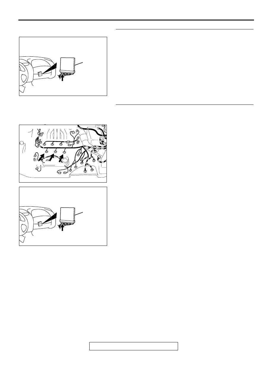
STEP 7. Check connector C-39 at PCM for damage.
Q: Is the connector in good condition?

YES : Go to Step 8.
NO :  Repair or replace it. Refer to GROUP 00E, Harness 

Connector Inspection (

P.00E-2

). Then go to Step 10.

STEP 8. Check for open circuit and short circuit to ground 
and harness damage between injector connector and PCM 
connector.

a. Check the harness wire between injector connector B-21 

terminal 2 and PCM connector C-39 terminal 9 when 
checking No.2 cylinder.

b. Check the harness wire between injector connector B-17 

terminal 2 and PCM connector C-39 terminal 2 when 
checking No.4 cylinder.

c. Check the harness wire between injector connector B-30 

terminal 2 and PCM connector C-39 terminal 25 when 
checking No.6 cylinder.

Q: Is the harness wire in good condition?

YES : Go to Step 9.
NO :  Repair it. Then go to Step 10.

AK000280

CONNECTOR : C-39

PCM

AW

AK000618 AD

CONNECTORS:B-17,B-21,B-30

B-30

B-17

B-21

AK000280

CONNECTOR : C-39

PCM

AW

MULTIPORT FUEL INJECTION(MFI) DIAGNOSIS

TSB Revision

MULTIPORT FUEL INJECTION (MFI) <3.0L>

13B-226

STEP 9. Using the oscilloscope, check the injector.
(1) Disconnect the injector connector B-21 <No.2 cylinder> or 

B-17 <No.4 cylinder> or B-30 <No.6 cylinder> and connect 
the test harness special tool (MB991348) in between. (All 
terminals should be connected)

(2) Connect the oscilloscope probe to the injector side 

connector terminal 2.

NOTE: When measuring with the PCM side connector, 
connect an oscilloscope probe to the each of the following 
terminals.

.

PCM terminal 9 when checking No.2 cylinder.

PCM terminal 2 when checking No.4 cylinder.

PCM terminal 25 when checking No.6 cylinder.

(3) Start the engine and run at idle.
(4) Measure the waveform.

The waveform should show a normal pattern similar to 
the illustration.

(5) Turn the ignition switch to the "LOCK"(OFF) position.

Q: Is the waveform normal?

YES : It can be assumed that this malfunction is intermittent. 

Refer to GROUP 00, How to Use Troubleshooting/
Inspection Service Points (

P.00-8

).

NO :  Replace the PCM. Then go to Step 10.

STEP 10. Test the OBD-II drive cycle.
(1) Carry out a test drive with the drive cycle pattern. Refer to, 

Procedure 6 

 Other Monitor(

P.13B-4

).

(2) Check the diagnostic trouble code (DTC).

Q: Is the DTC P0202, P0204, P0206 is output?

YES : Retry the troubleshooting.
NO :  The inspection is complete.

DTC P0300: Random Misfire Detected

Random Misfire Circuit

Refer to, DTC P0201,P0203,P0205 

 Injector 

Circuit (

P.13B-212

).

Refer to, DTC P0202,P0204,P0206 

 Injector 

Circuit (

P.13B-220

).

CIRCUIT OPERATION

Refer to, DTC P0201,P0203,P0205 

 Injector 

Circuit (

P.13B-212

).

Refer to, DTC P0202,P0204,P0206 

 Injector 

Circuit (

P.13B-220

).

TECHNICAL DESCRIPTION

If a misfire occurs while the engine is running, the 
engine speed changes for an instant.

The PCM checks for such changes in engine 
speed.

DTC SET CONDITIONS

Check Conditions

Five seconds or more have passed after the 
engine was started.

Engine speed is between 440 and 6,000 r/min.

Engine coolant temperature is higher than -10

° 

(14

° 

F).

Intake air temperature is higher than -10

° 

C (14

° 

F).

Barometric pressure is higher than 76 kPa (11 
psi).

Adaptive learning is complete for the vane which 

generates a crankshaft position signal.

AK000587

OSCILLOSCOPE

OSCILLO

SCOPE

PROBE

1

2

AB

INJECTOR
CONNECTOR

AKX01557 AB

A

NORMAL  WAVEFORM

A:INJECTOR DRIVE TIME

MULTIPORT FUEL INJECTION(MFI) DIAGNOSIS

TSB Revision

MULTIPORT FUEL INJECTION (MFI) <3.0L>

13B-227

While the engine is running, excluding gear 
shifting, deceleration, sudden acceleration/
deceleration and A/C compressor switching.

Vehicle speed is 2.5km (1.6mph) or more.

The throttle deviation is -0.059V/10ms to 
+0.059V/10ms.

Judgement Criteria (change in the angular 

acceleration of the crankshaft is used for 
misfire detection).

Misfire has occurred in 4 or more of the last 200 
revolutions [when the catalyst temperature is 
higher than 950

°

 C (1742

° 

F)].

or

Misfire has occurred in 20 or more of the last 
1,000 revolutions (corresponding to 1.5 times the 
limit of emission standard).

TROUBLESHOOTING HINTS (The most likely 
causes for this code to be set are:)

Ignition system related part(s) failed.

Poor crankshaft position sensor.

Incorrect air/fuel ratio.

Low compression pressure.

Skipping of timing belt teeth.

EGR system and EGR valve failed.

PCM failed.

DIAGNOSIS

Required Special Tools
MB991502: Scan Tool (MUT-II)

STEP 1. Using scan tool MB991502, check data list item 22: 
Crankshaft Position Sensor.

CAUTION

To prevent damage to scan tool MB991502, always turn the 
ignition switch to the "LOCK"(OFF) position before 
connecting or disconnecting scan tool MB991502.
(1) Connect scan tool MB991502 to the data link connector.
(2) Start the engine and run at idle.
(3) Set scan tool MB991502 to the data reading mode for item 

22, Crankshaft Position Sensor.

(4) Check the waveform of the crankshaft position sensor while 

keeping the engine speed constant.

The pulse width should be constant.

(5) Turn the ignition switch to "LOCK"(OFF) position.

Q: Is the sensor operating properly?

YES : Go to Step 2.
NO :  Refer to, DTC P0335 

 Crankshaft Position Sensor 

Circuit Malfunction(

P.13B-240

).

AC003081 AB

16 PIN

MB991502

MULTIPORT FUEL INJECTION(MFI) DIAGNOSIS

TSB Revision

MULTIPORT FUEL INJECTION (MFI) <3.0L>

13B-228

STEP 2. Using scan tool MB991502, check data list item 81 
<bank 1> and 83 <bank 2>: Long 

−−−−

 Term Fuel 

Compensation (trim).
(1) Start the engine and run at idle.
(2) Set scan tool MB991502 to the data reading mode for item 

81 <bank 1> and 83 <bank 2>, Long 

 Term Fuel 

Compensation (trim).

The fuel trim should be between -12.5 and +12.5 when 
the load is 2,500 r/min (during closed loop) after the 
engine is warmed.

(3) Turn the ignition switch to "LOCK"(OFF) position.

Q: Is the specification normal?

YES : Go to Step 3.
NO :  Refer to, DTC P0171 

 System too Lean (bank 

1)(

P.13B-191

), DTC P0172 

 System too Rich (bank 

1)(

P.13B-198

), DTC P0174 

 System too Lean (bank 

2)(

P.13B-203

), DTC P0175 

 System too Rich (bank 

2)(

P.13B-208

).

STEP 3. Using scan tool MB991502, check data list item 
82<bank 1> and 84 <bank 2>: Short 

−−−−

 Term Fuel 

Compensation (trim) Bank 1.
(1) Start the engine and run at idle.
(2) Set scan tool MB991502 to the data reading mode for item 

82 <bank 1> and 84 <bank 2>, Short 

 Term Fuel 

Compensation (trim).

The fuel trim should be between -25 and +25 when the 
load is 2,500 r/min (during closed loop) after the engine 
is warmed.

(3) Turn the ignition switch to "LOCK"(OFF) position.

Q: Is the specification normal?

YES : Go to Step 4.
NO :  Refer to, DTC P0171 

 System too Lean (bank 

1)(

P.13B-191

), DTC P0172 

 System too Rich (bank 

1)(

P.13B-198

), DTC P0174 

 System too Lean (bank 

2)(

P.13B-203

), DTC P0175 

 System too Rich (bank 

2)(

P.13B-208

).

STEP 4. Check the ignition coil spark
(1) Check each ignition coil spark.
(2) Remove the intake manifold.
(3) Remove the spark plug and connect to the spark plug 

cable.

(4) Ground the spark plug side electrode securely.

When the engine is cranked, the spark plug should 
spark.

Q: Did it spark?

YES : Go to Step 7.
NO :  Go to Step 5.

AC003081 AB

16 PIN

MB991502

AC003081 AB

16 PIN

MB991502

AKX00432

SPARK PLUG

AB


Content   ..  248  249  250  251   ..