Mitsubishi Galant. Manual - part 248
 

  Index      Mitsubishi     Mitsubishi Galant - service repair manual 2001 year


Search            


Content   ..  246  247  248  249   ..


Mitsubishi Galant. Manual - part 248


MULTIPORT FUEL INJECTION(MFI) DIAGNOSIS

TSB Revision

MULTIPORT FUEL INJECTION (MFI) <3.0L>

13B-217

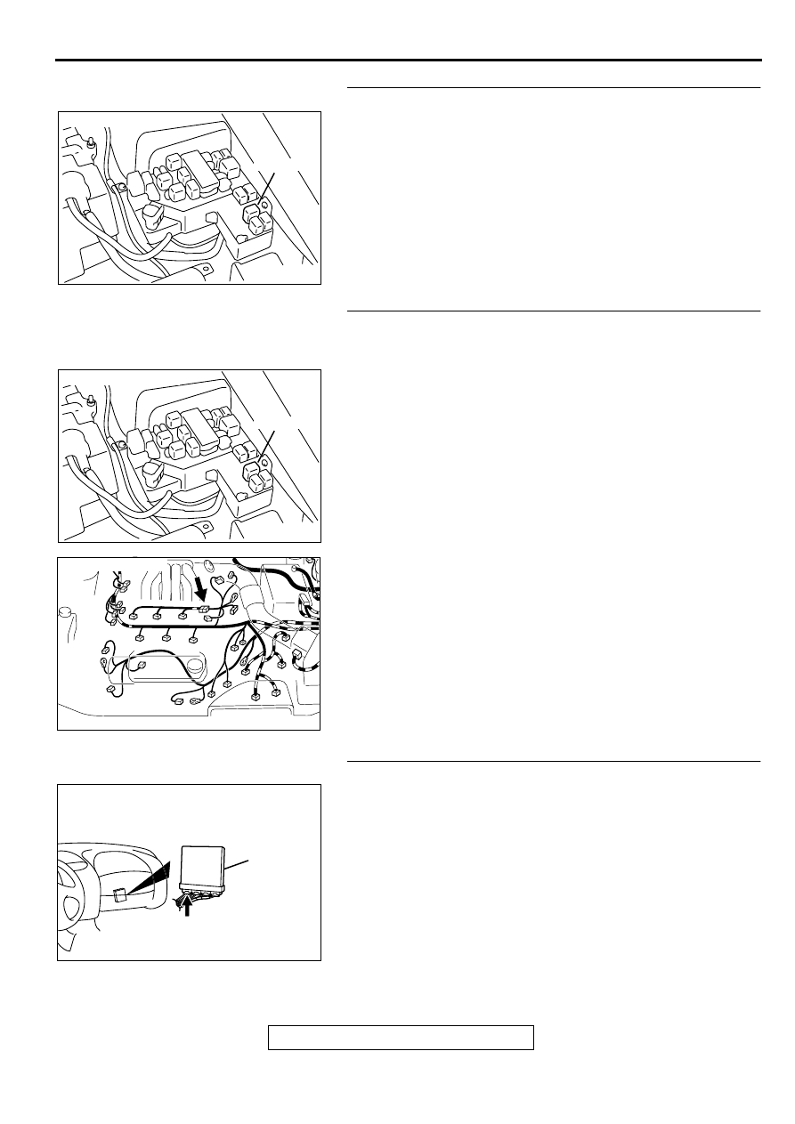
STEP 7. Check connector A-21X at MFI relay for damage.
Q: Is the connector in good condition?

YES : Repair harness wire between MFI relay connector A-

21X terminal 1 and injector intermediate connector B-
26 terminal 1 because of open circuit or short circuit to 
ground. Then go to Step 12. 

NO :  Repair or replace it. Refer to GROUP 00E, Harness 

Connector Inspection (

P.00E-2

). Then go to Step 12.

STEP 8. Check for harness damage between MFI relay 
connector A-21X terminal 1 and injector intermediate 
connector B-26 terminal 1.
Q: Is the harness wire in good condition?

YES : Go to Step 9.
NO :  Repair it. Then go to Step 12.

STEP 9. Check connector C-39 at PCM for damage.
Q: Is the connector in good condition?

YES : Go to Step 10.
NO :  Repair or replace it. Refer to GROUP 00E, Harness 

Connector Inspection (

P.00E-2

). Then go to Step 12.

AK000555AB

CONNECTOR : A-21X

MFI RELAY

AK000555AB

CONNECTOR : A-21X

MFI RELAY

AK000618

AB

CONNECTOR:B-26

AK000280

CONNECTOR : C-39

PCM

AW

MULTIPORT FUEL INJECTION(MFI) DIAGNOSIS

TSB Revision

MULTIPORT FUEL INJECTION (MFI) <3.0L>

13B-218

STEP 10. Check for open circuit and short circuit to 
ground and harness damage between injector 
intermediate connector and PCM connector.

a. Check the harness wire between intermediate connector B-

26 terminal 2 and PCM connector C-39 terminal 1 when 
checking No.1 cylinder.

b. Check the harness wire between intermediate connector B-

26 terminal 3 and PCM connector C-39 terminal 24 when 
checking No.3 cylinder.

c. Check the harness wire between intermediate connector B-

26 terminal 4 and PCM connector C-39 terminal 10 when 
checking No.5 cylinder.

Q: Is the harness wire in good condition?

YES : Go to Step 11.
NO :  Repair it. Then go to Step 12.

AK000618

AB

CONNECTOR:B-26

AK000280

CONNECTOR : C-39

PCM

AW

MULTIPORT FUEL INJECTION(MFI) DIAGNOSIS

TSB Revision

MULTIPORT FUEL INJECTION (MFI) <3.0L>

13B-219

STEP 11. Using the oscilloscope, check the injector.
(1) Disconnect the injector intermediate connector B-26 and 

connect the test harness special tool (MD998464) in 
between.

(2) Connect the oscilloscope probe to each injector 

intermediate connector terminal to oscilloscope each 
cylinder:

•

Terminal 2 (black clip) when checking No.1 cylinder.

•

Terminal 3 (blue clip) when checking No.3 cylinder.

•

Terminal 4 (white clip) when checking No.5 cylinder.

NOTE: When measuring with the PCM side connector, 
connect an oscilloscope probe to the each of the following 
terminals.

.

•

PCM terminal 1 when checking No.1 cylinder injector

•

PCM terminal 24 when checking No.3 cylinder injector

•

PCM terminal 10 when checking No.5 cylinder injector

(3) Start the engine and run at idle.
(4) Measure the waveform.

•

The waveform should show a normal pattern similar to 
the illustration.

(5) Turn the ignition switch to the "LOCK"(OFF) position.

Q: Is the waveform normal?

YES : It can be assumed that this malfunction is intermittent. 

Refer to GROUP 00, How to Use Troubleshooting/
Inspection Service Points (

P.00-8

).

NO :  Replace the PCM. Then go to Step 12.

STEP 12. Test the OBD-II drive cycle.
(1) Carry out a test drive with the drive cycle pattern. Refer to, 

Procedure 6 

−

 Other Monitor(

P.13B-4

).

(2) Check the diagnostic trouble code (DTC).

Q: Is the DTC P0201, P0203, P0205 is output?

YES : Retry the troubleshooting.
NO :  The inspection is complete.

AK000063

1 2

3 4

OSCILLOSCOPE

INJECTOR INTERMEDIATE
CONNECTOR

OSCILLO

SCOPE

PROBE

AB

AKX01557 AB

A

NORMAL  WAVEFORM

A:INJECTOR DRIVE TIME

MULTIPORT FUEL INJECTION(MFI) DIAGNOSIS

TSB Revision

MULTIPORT FUEL INJECTION (MFI) <3.0L>

13B-220

DTC P0202: Injector Circuit Malfunction 

−−−−

 Cylinder 2 DTC P0204: Injector Circuit Malfunction 

−−−−


Cylinder 4 DTC P0206: Injector Circuit Malfunction 

−−−−

 Cylinder 6

AK000509

1 2
3

RED-

WHITE

YELLO

W

-RED

GREEN-BLA

CK

GREEN-WHITE

RED

RED

RED

RED-

WHITE

RED-

WHITE

4

RED

25

9

A-21X

2

POWERTRAIN CONTROL
MODULE(PCM)

1

1

1

2

2

2

INJECTOR
NO.2

B-21

INJECTOR
NO.4

INJECTOR
NO.6

MFI
RELAY

BATTERY

1

2

3

4

      C-39
(MU803784)

2

3 4

5 6

7 8

9

11 12 13 14 15 16 17 18 19 20

30

21 22 23

24 25

26 27 28 29

3132 33

34 35

1

10

2

1

B-17

2

1

B-30

2

1


Content   ..  246  247  248  249   ..