Mitsubishi Galant. Manual - part 115


  Index      Mitsubishi     Mitsubishi Galant - service repair manual 2001 year


Search            


Content   ..  113  114  115  116   ..


Mitsubishi Galant. Manual - part 115


MULTIPORT FUEL INJECTION(MFI) DIAGNOSIS

TSB Revision

MULTIPORT FUEL INJECTION (MFI) <2.4L>

13A-141

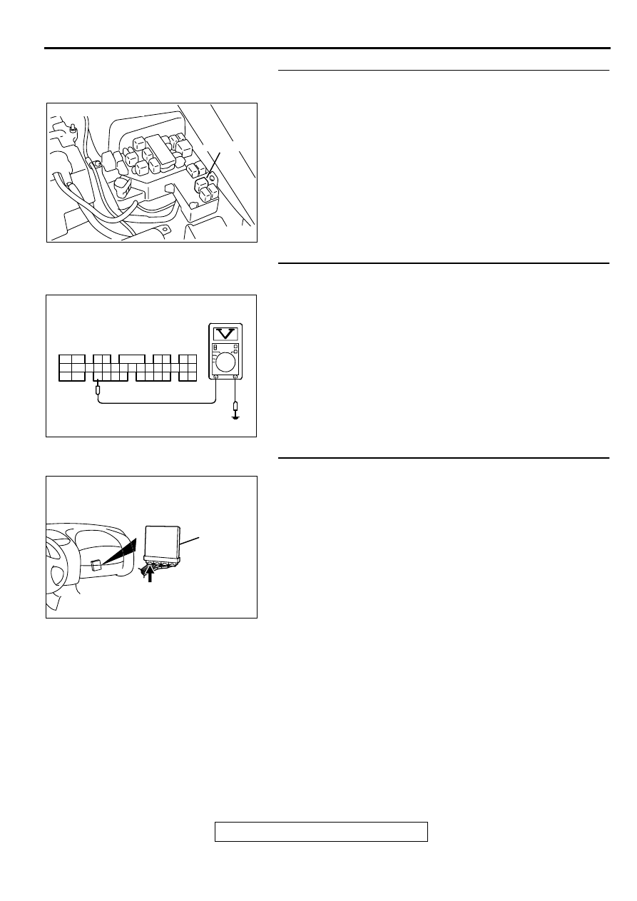
STEP 4. Check harness connector A-21X at the MFI relay 
for damage.
Q: Is the connector in good condition?

YES : Repair harness wire between MFI relay connector A-

21X terminal 1 and heated oxygen sensor (rear) 
connector C-19 terminal 5 because of open circuit or 
short circuit to ground. Then go to Step 12.

NO :  Repair or replace it. Refer to GROUP 00E, Harness 

Connector Inspection (

P.00E-2

). Then go to Step 12.

STEP 5. Check the power supply voltage at PCM connector 
C-39 by backprobing.
(1) Do not disconnect the connector C-39.
(2) Turn the ignition switch to the "ON" position.
(3) Measure the voltage between terminal 26 and ground by 

backprobing.

Voltage should be battery positive voltage.

(4) Turn the ignition switch to the "LOCK" (OFF) position.

Q: Is the voltage normal?

YES : Go to Step 8.
NO :  Go to Step 6.

STEP 6. Check connector C-39 at PCM for damage.
Q: Is the connector in good condition?

YES : Go to Step 7.
NO :  Repair or replace it. Refer to GROUP 00E, Harness 

Connector Inspection (

P.00E-2

). Then go to Step 12.

AK000555AB

CONNECTOR : A-21X

MFI RELAY

AK000295

C-39 CONNECTOR
HARNESS SIDE VIEW

1
9

24

2

10 11
25

3

12
26

4

13
27

5

19
32

6

20 21
33

7

22
34

8

23
35

14
28

1516
29

17

30

18

31

AC

AK000280

CONNECTOR : C-39

PCM

AW

MULTIPORT FUEL INJECTION(MFI) DIAGNOSIS

TSB Revision

MULTIPORT FUEL INJECTION (MFI) <2.4L>

13A-142

STEP 7. Check for open circuit or short circuit to ground 
between heated oxygen sensor (rear) connector C-19 
terminal 6 and PCM connector C-39 terminal 26.
Q: Is the harness wire in good condition?

YES : Replace the PCM. Then go to Step 12.
NO :  Repair it. Then go to Step 12.

STEP 8. Check connector C-39 at PCM for damage.
Q: Is the connector in good condition?

YES : Go to Step 9.
NO :  Repair or replace it. Refer to GROUP 00E, Harness 

Connector Inspection (

P.00E-2

). Then go to Step 12.

AK000558AB

CONNECTOR:C-19

AK000280

CONNECTOR : C-39

PCM

AW

AK000280

CONNECTOR : C-39

PCM

AW

MULTIPORT FUEL INJECTION(MFI) DIAGNOSIS

TSB Revision

MULTIPORT FUEL INJECTION (MFI) <2.4L>

13A-143

STEP 9. Check for harness damage between MFI relay 
connector A-21X terminal 1 and heated oxygen sensor 
(rear) connector C-19 terminal 5.
Q: Is the harness wire in good condition?

YES : Go to Step 10.
NO :  Repair it. Then go to Step 12.

STEP 10. Check for harness damage between heated 
oxygen sensor (rear) connector C-19 terminal 6 and PCM 
connector C-39 terminal 26.
Q: Is the harness wire in good condition?

YES : Go to Step 11.
NO :  Repair it. Then go to Step 12.

AK000555AB

CONNECTOR : A-21X

MFI RELAY

AK000558AB

CONNECTOR:C-19

AK000558AB

CONNECTOR:C-19

AK000280

CONNECTOR : C-39

PCM

AW

MULTIPORT FUEL INJECTION(MFI) DIAGNOSIS

TSB Revision

MULTIPORT FUEL INJECTION (MFI) <2.4L>

13A-144

STEP 11. Check the trouble symptoms.
(1) Carry out a test drive with the drive cycle pattern. Refer to, 

Procedure 6 

 Other Monitor(

P.13A-5

).

(2) Check the diagnostic trouble code (DTC).

Q: Is the DTC P0141 is output?

YES : Replace the PCM. Then go to Step 12.
NO :  It can be assumed that this malfunction is intermittent. 

Refer to GROUP 00, How to Use Troubleshooting/
Inspection Service Points(

P.00-8

).

STEP 12. Test the OBD-II drive cycle.
(1) Carry out a test drive with the drive cycle pattern. Refer to, 

Procedure 6 

 Other Monitor(

P.13A-5

).

(2) Check the diagnostic trouble code (DTC).

Q: Is the DTC P0141 is output?

YES : Retry the troubleshooting.
NO :  The inspection is complete.

DTC P0171: System too Lean

Fuel Trim Circuit

Refer to, P0201_P0204 Injector Circuit (

P.13A-

154

).

CIRCUIT OPERATION

Refer to, P0201_P0204 Injector Circuit (

P.13A-

154

).

TECHNICAL DESCRIPTION

If a malfunction occurs in the fuel system, the fuel 
trim value becomes too large.

The PCM checks whether the fuel trim value is 
within a specified range.

DTC SET CONDITIONS

Check Conditions

Engine coolant temperature is lower than 
approximately 100

°

 C (212

°

 F) when the engine 

is started.

Intake air temperature is lower than 60

°

 C (140

°


F) when the engine is started.

Under the closed loop air/fuel ratio control.

Intake air temperature is higher than -10

° 

C (14

° 

F).

Barometric pressure is higher than 76kPa (11 
psi).

Volume air flow sensor output frequency is 88 Hz 
or more.

Judgment Criteria

Long-term fuel trim has continued to be higher 
than +12.5 for 2 seconds.

or

Short-term fuel trim has continued to be higher 
than +10.0 for 2 seconds.

Check Conditions

Engine coolant temperature is lower than 
approximately 100

°

 C (212

°

 F) when the engine 

is started.

Intake air temperature is lower than 60

°

 C (140

°


F) when the engine is started.

Under the closed loop air/fuel ratio control.

Intake air temperature is higher than -10

° 

C (14

° 

F).

Barometric pressure is higher than 76kPa (11 
psi).

Volume air flow sensor output frequency is 88 Hz 
or less.

Judgment Criteria

Long-term fuel trim has continued to be higher 
than +12.5 for 2 seconds.

or

Short-term fuel trim has continued to be higher 
than +15.0 for 2 seconds.

Check Conditions

Engine coolant temperature is higher than 
approximately 100

°

 C (212

°

 F) when the engine 

is started.


Content   ..  113  114  115  116   ..