Mitsubishi Galant. Manual - part 111
 

  Index      Mitsubishi     Mitsubishi Galant - service repair manual 2001 year


Search            


Content   ..  109  110  111  112   ..


Mitsubishi Galant. Manual - part 111


MULTIPORT FUEL INJECTION(MFI) DIAGNOSIS

TSB Revision

MULTIPORT FUEL INJECTION (MFI) <2.4L>

13A-125

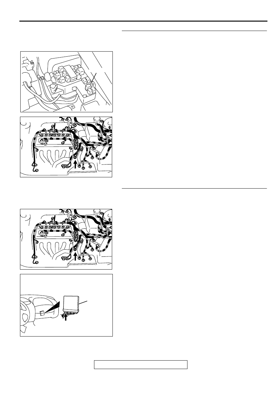
STEP 9. Check for harness damage between MFI relay 
connector A-21X terminal 1 and heated oxygen sensor 
(front) connector B-15 terminal 1.
Q: Is the harness wire in good condition?

YES : Go to Step 10.
NO :  Repair it. Then go to Step 12.

STEP 10. Check for harness damage between heated 
oxygen sensor (front) connector B-15 terminal 3 and PCM 
connector C-39 terminal 3.
Q: Is the harness wire in good condition?

YES : Go to Step 11.
NO :  Repair it. Then go to Step 12.

AK000555AB

CONNECTOR : A-21X

MFI RELAY

AK000556 AB

CONNECTOR:B-15

AK000556 AB

CONNECTOR:B-15

AK000280

CONNECTOR : C-39

PCM

AW

MULTIPORT FUEL INJECTION(MFI) DIAGNOSIS

TSB Revision

MULTIPORT FUEL INJECTION (MFI) <2.4L>

13A-126

STEP 11. Check the trouble symptoms.
(1) Carry out a test drive with the drive cycle pattern. Refer to, 

Procedure 6 

−

 Other Monitor(

P.13A-5

).

(2) Check the diagnostic trouble code (DTC).

Q: Is the DTC P0135 is output?

YES : Replace the PCM. Then go to Step 12.
NO :  It can be assumed that this malfunction is intermittent. 

Refer to GROUP 00, How to Use Troubleshooting/
Inspection Service Points(

P.00-8

).

STEP 12. Test the OBD-II drive cycle.
(1) Carry out a test drive with the drive cycle pattern. Refer to, 

Procedure 6 

−

 Other Monitor(

P.13A-5

).

(2) Check the diagnostic trouble code (DTC).

Q: Is the DTC P0135 is output?

YES : Retry the troubleshooting.
NO :  The inspection is complete.

MULTIPORT FUEL INJECTION(MFI) DIAGNOSIS

TSB Revision

MULTIPORT FUEL INJECTION (MFI) <2.4L>

13A-127

DTC P0136: O

2

  Sensor Circuit Malfunction (sensor 2)

AK000466

BLA

CK

BLA

CK

GREEN

FROM MFI RELAY

HEATED OXYGEN
SENSOR(REAR)

     C-19
MU801448

TO ECM
OR PCM

POWERTRAIN CONTROL
MODULE(PCM)

73

57

      C-40
(MU803781)

      C-41
(MU803782)

5

6

4

3

1

2

3 4 5 6

98

78

71

88 89

76 77

72
79

91

73
80

74

75

81

92

82 83
93

84 85

94

86 87

95 96

90

97

42 43
48 49 50 51 52 53 54 55 56 57

46

45

44

58 59

60 61 62 63

64 65 66

47

41

MULTIPORT FUEL INJECTION(MFI) DIAGNOSIS

TSB Revision

MULTIPORT FUEL INJECTION (MFI) <2.4L>

13A-128

CIRCUIT OPERATION

•

A voltage corresponding to the oxygen 
concentration in the exhaust gas is sent to the 
PCM (terminal 73) from the output terminal 
(terminal 3) of the heated oxygen sensor (rear).

•

Terminal 4 of the heated oxygen sensor (rear) is 
grounded with PCM (terminal 57).

TECHNICAL DESCRIPTION

•

The output signal of the heated oxygen sensor 
(front) is compensated by the output signal of the 
heated oxygen sensor (rear).

•

The PCM checks for an open circuit in the heated 
oxygen sensor (rear) output line.

DTC SET CONDITIONS

Check Conditions

•

Heated oxygen sensor (rear) signal voltage has 
continued to be 0.15 volt or lower for three 
minutes or more after the starting sequence was 
completed.

•

Engine coolant temperature is higher than 82

°

 C 

(180

°

 F).

•

Engine speed is higher than 1,200 r/min.

•

Volumetric efficiency is higher than 25 percent.

•

Monitoring time: 7 seconds.

Judgment Criteria

•

Input voltage supplied to the PCM interface 
circuit is higher than 4.5 volts when 5 volts is 
applied to the heated oxygen sensor (rear) output 
line via a resistor.

•

Only one monitor during one drive cycle

Check Conditions

•

Heated oxygen sensor (rear) signal voltage has 
continued to be 0.15 volt or lower for three 
minutes or more after the starting sequence was 
completed.

•

Engine coolant temperature is higher than 82

°

 C 

(180

° 

F).

•

Engine speed is higher than 1,200 r/min.

•

Volumetric efficiency is higher than 25 percent.

•

Volume air flow sensor output frequency is 88 Hz 
or more.

•

At least twenty seconds have passed since fuel 
shut off control was canceled.

•

The heated oxygen sensor (front) outputs 0.5 
volts or more.

•

Monitoring time: 10 seconds

Judgement Criteria

•

Making the air/fuel ratio 15 percent for 10 
seconds richer does not result in raising the 
heated oxygen sensor (rear) output voltage 
beyond 0.15 volt.

•

Only one monitor during one drive cycle

TROUBLESHOOTING HINTS (The most likely 
causes for this code to be set are:)

•

Heated oxygen sensor (rear) failed.

•

Open circuit in heated oxygen sensor (rear) 
output line.

•

Open circuit in heated oxygen sensor (rear) 
ground line.

•

PCM failed.

DIAGNOSIS

Required Special Tools
MB991502: Scan Tool (MUT-II)
MB991658: Test Harness

AC002318

CONNECTOR:C-19

HEATED
OXYGEN
SENSOR
(REAR)

AC

AK000280

CONNECTORS : C-40, C-41

C-41

C-40

PCM

AX


Content   ..  109  110  111  112   ..