Mitsubishi Galant. Manual - part 110
MULTIPORT FUEL INJECTION(MFI) DIAGNOSIS
TSB Revision
MULTIPORT FUEL INJECTION (MFI) <2.4L>
13A-121
CIRCUIT OPERATION
•
Power is supplied from the MFI relay (terminal 1)
to the heated oxygen sensor (front) heater.
•
The PCM (terminal 3) controls continuity to the
heated oxygen sensor (front) heater by turning
the power transistor in the PCM "ON" and
"OFF."
TECHNICAL DESCRIPTION
•
The PCM checks whether the heater current is
within a specified range when the heater is
energized.
DTC SET CONDITIONS
Check Conditions
•
Engine coolant temperature is higher than 20
°
C
(68
°
F).
•
While the heated oxygen sensor (front) heater is
on.
•
Battery positive voltage is at between 11 and 16
volts.
Judgment Criteria
•
Heater current of the heated oxygen sensor
(front) heater has continued to be lower than 0.2
ampere or higher than 3.5 ampere for 6 seconds.
•
One monitor during one drive cycle
TROUBLESHOOTING HINTS (The most likely
causes for this code to be set are:)
•
Open or shorted heated oxygen sensor (front)
heater circuit.
•
Open circuit in heated oxygen sensor (front)
heater.
•
PCM failed.
DIAGNOSIS
Required Special Tools
MD998464: Test Harness
ACX02476
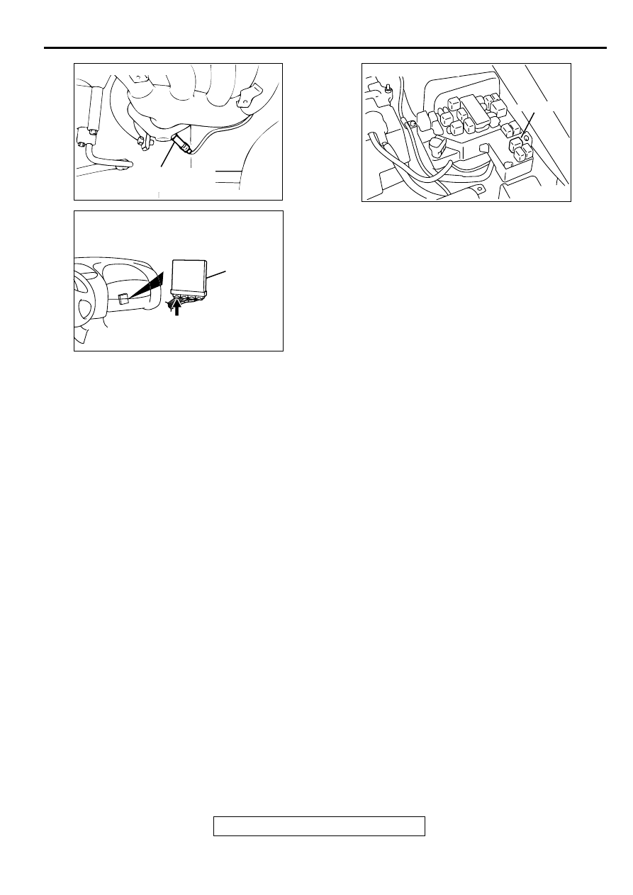
CONNECTOR : B-15
AF
HEATED OXYGEN
SENSOR (FRONT)
AK000280
CONNECTOR : C-39
PCM
AW
AK000555AB
CONNECTOR : A-21X
MFI RELAY