Mitsubishi Galant. Manual - part 74


  Index      Mitsubishi     Mitsubishi Galant - service repair manual 2001 year


Search            


Content   ..  72  73  74  75   ..


Mitsubishi Galant. Manual - part 74


PISTON AND CONNECTING ROD

TSB Revision

ENGINE OVERHAUL <3.0L>

11D-45

INSTALLATION SERVICE POINTS

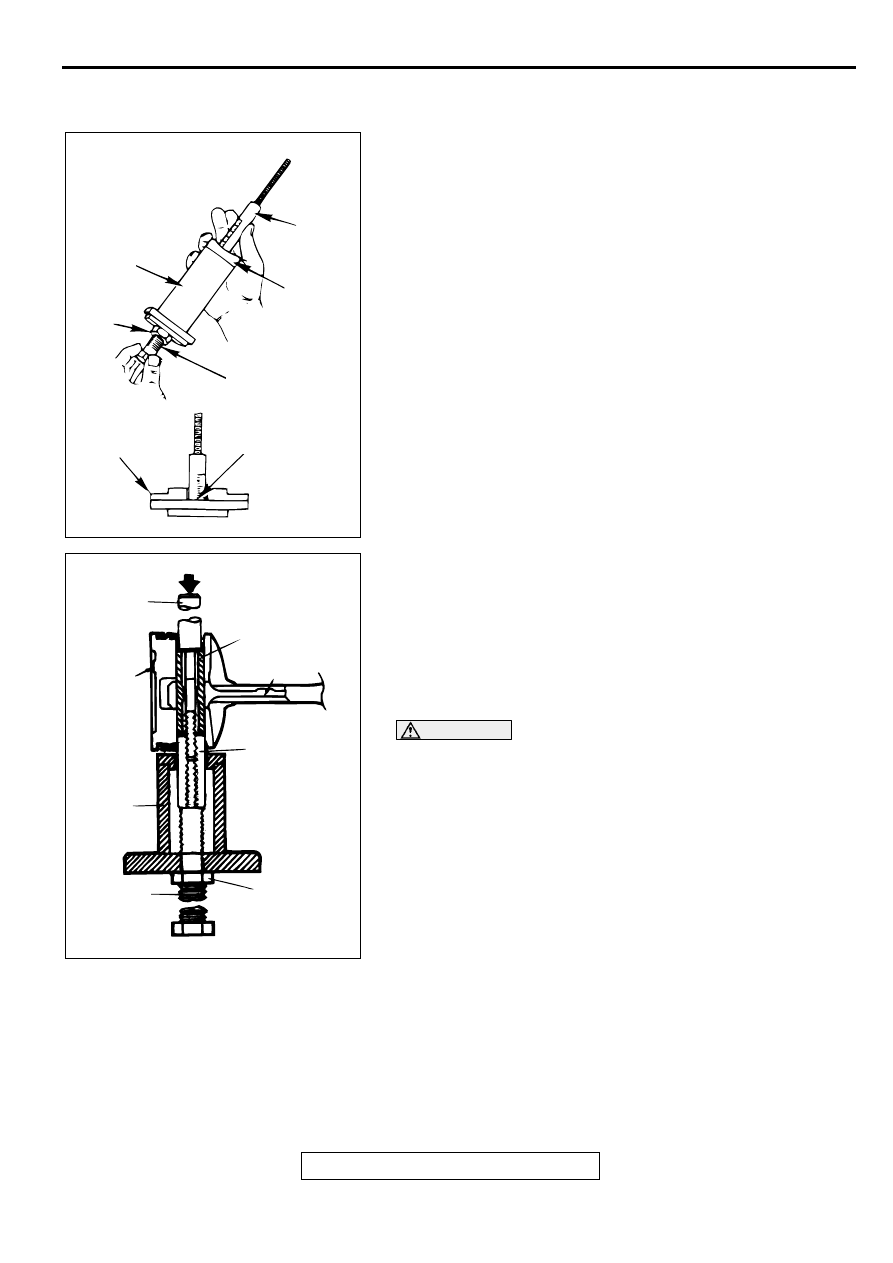
>>A<< PISTON PIN INSTALLATION
1. Thread the stop screw and jam nut assembly into the base. 

Fit the correct piston support on top of the base. Insert the 
press pin, threaded end up, into the hole in the piston 
support until the press pin touches the stop screw.

2. Using the graduations on the press pin, adjust the stop 

screw to the depth.

Depth: 60 mm (2.36 inches)

3. Place the base on the press support blocks.

4. Slide the piston pin over the threaded end of the press pin, 

and thread the correct guide pin up against it.

5. Coat the piston pin with engine oil, and with the connecting 

rod held in position, slide the guide pin through the piston 
and connecting rod.

6. Press the piston pin through the connecting rod until the 

guide pin contacts the stop screw.

CAUTION

Due to production tolerance variations, it is necessary to 
visually inspect the piston pin depth after installation to 
verify that the piston pin is centered. Adjust if necessary.
7. Remove the piston assembly from the base. Remove the 

guide pin and press pin from the assembly.

AKX00732

PRESS
PIN

PISTON 
SUPPORT

STOP 
SCREW

PIN DEPTH SET
LOCATION

FLAT PISTON
SUPPORT

JAM
NUT

BASE

AB

AKX00646

JAM NUT

PRESS 
PIN

PISTON PIN

FRONT
MARK

FRONT
MARK

CONNECTING
ROD GUIDE
PIN

BASE

STOP
SCREW

AB

PISTON AND CONNECTING ROD

TSB Revision

ENGINE OVERHAUL <3.0L>

11D-46

8. Check that the piston moves smoothly.

>>B<< OIL RING INSTALLATION
1. Fit the oil ring spacer into the piston ring groove.

NOTE: The side rails and spacer may be installed in either 
direction.

NOTE: New spacers and side rails are colored for 
identification of their sizes.

CAUTION

Do not use any piston ring expander when installing the 
side rail.
2. Install the upper side rail 

To install the side rail, first fit one end of the rail into the 
piston groove, then press the remaining portion into the 
position by finger. See illustration. 

3. Install the lower side rail in the same procedure as described 

in step 2.

4. Make sure that the side rails move smoothly in either 

direction.

AKX00716

SIZE

COLOR

Standard

None

0.50 mm (0.020 in) oversize

Blue

1.00 mm (0.040 in) oversize

Yellow

AK000196AB

SIDE RAIL

SIDE RAIL

SPACER

AKX00608

SIDE RAIL END

AB

PISTON AND CONNECTING ROD

TSB Revision

ENGINE OVERHAUL <3.0L>

11D-47

>>C<< PISTON RING NO.2/PISTON RING NO.1 
INSTALLATION
1. To prevent wrong installation, check the identification mark 

of each piston ring. The identification mark is stamped near 
the ring gap:

Identification mark

Number 1 ring: T
Number 2 ring: 2T

NOTE: Size marks on piston rings are as follows.

2. Using a piston ring expander, fit the number 2 piston ring 

into the number 2 groove of piston.

NOTE: Install the piston rings with their identification mark 
facing up, to the piston crown side.

3. Install the number 1 piston ring in the same manner as step 

2.

>>D<< PISTON AND CONNECTING ROD INSTALLATION
1. Apply engine oil on the circumference of the piston, piston 

rings, and oil ring.

2. Arrange the piston ring and oil ring gaps (side rail and 

spacer) as shown in the illustration.

3. Rotate the crankshaft so that the crank pin is on the center 

of the cylinder bore.

4. Use suitable thread protectors on the connecting rod bolts 

before inserting the piston and connecting rod assembly into 
the cylinder block. 
Care must be taken not to nick the crank pin.

5. Insert the piston and connecting rod assembly into the 

cylinder with the front mark on the piston crown pointing to 
the timing belt side.

6. Using a suitable piston ring compressor tool, install the 

piston and connecting rod assembly into the cylinder block.

SIZE

SIZE MARK

Standard

None

0.50 mm (0.020 in) oversize

50

1.00 mm (0.040 in) oversize

100

AKX00689

NO.1

NO.2

IDENTIFICATION 
MARK

SIZE MARK

IDENTIFICATION MARK

AB

AKX00633

AKX00620

UPPER
SIDE RAIL

NO.1

PISTON PIN

TIMING
BELT SIDE

LOWER
SIDE RAIL

NO.2 RING GAP 
AND SPACER GAP

AB

AKX00721

PISTON AND CONNECTING ROD

TSB Revision

ENGINE OVERHAUL <3.0L>

11D-48

>>E<< CONNECTING ROD CAP INSTALLATION
1. Mate the correct bearing cap with the correct connecting rod 

by checking with the alignment marks marked during 
disassembly. If a new connecting rod is used which has no 
alignment mark, position the notches for locking the bearing 
on the same side.

2. Check if the thrust clearance in the connecting rod big end is 

correct.

Standard value: 0.10 

−−−−

 0.25 mm (0.004 

−−−−

 0.009 inch)

Limit: 0.4 mm (0.02 inch)

INSPECTION

M1113008500042

PISTON
Replace the piston if scratches or seizure is evident on its 
surfaces (especially the thrust surface). Replace the piston if it 
is cracked.

PISTON PIN
1. Insert the piston pin into the piston pin hole with your thumb. 

You should feel a slight resistance. Replace the piston pin if 
it can be easily inserted or there is an excessive play.

2. The piston and piston pin must be replaced as an assembly.

PISTON RING 
1. Check the piston ring for damage, excessive wear, and 

breakage. Replace if defects are evident. If the piston has 
been replaced, the piston rings must also be replaced.

2. Check for clearance between the piston ring and ring 

groove. If it exceeds the limit, replace the ring or piston, or 
both.

Standard value: 

Number 1 0.03 

−−−−

 0.07 mm (0.0012 

−−−−

 0.0027 inch)

Number 2 0.02 

−−−−

 0.06 mm (0.0008 

−−−−

 0.0023 inch)

Limit: 0.1 mm (0.003 inch)

AKX00735

CYLINDER NO.

NOTCHES

AB

AKX00736

AKX00612


Content   ..  72  73  74  75   ..