Mitsubishi Galant. Manual - part 73
OIL PAN AND OIL PUMP
TSB Revision
ENGINE OVERHAUL <3.0L>
11D-41
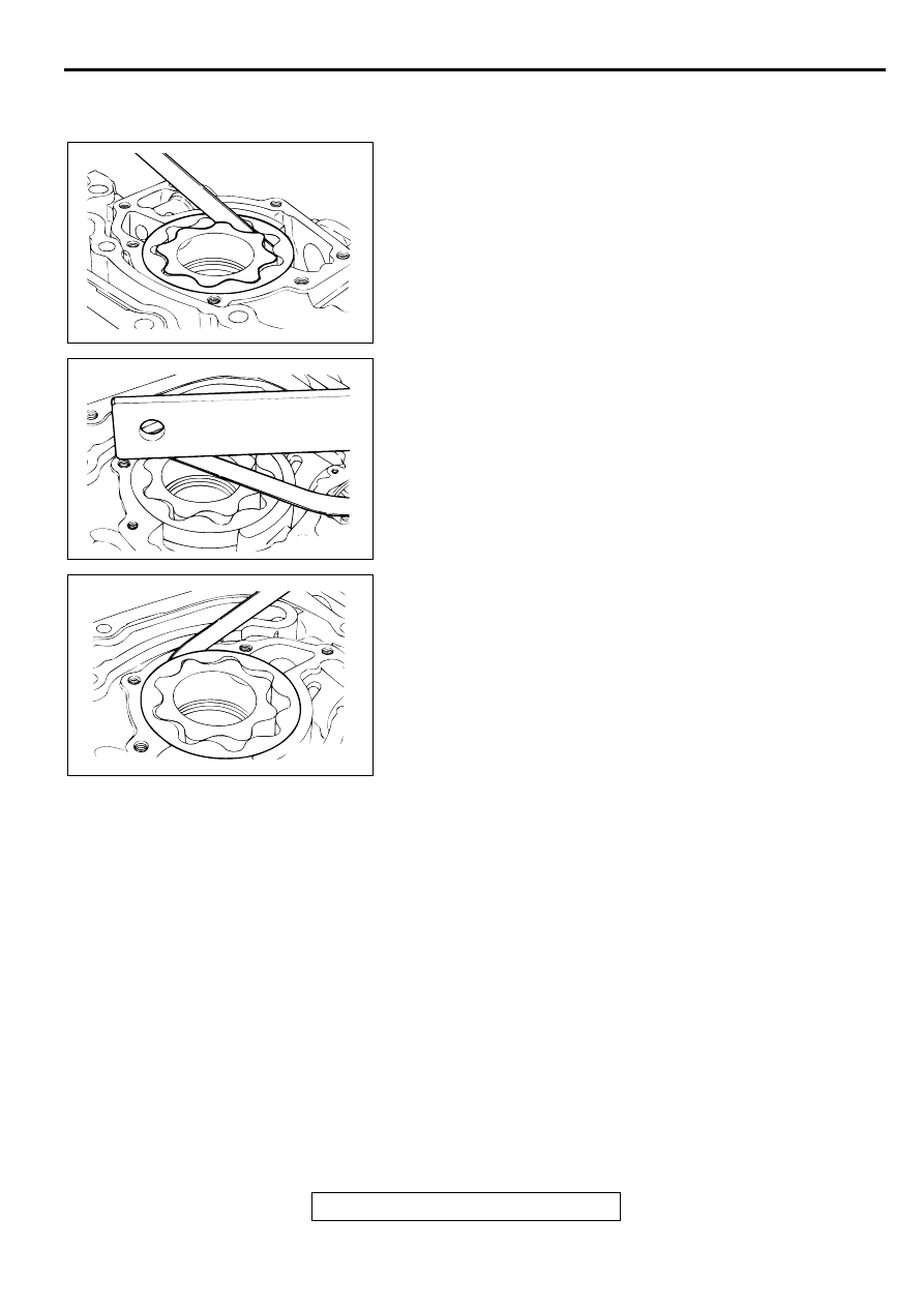
INSPECTION
M1113008200030
OIL PUMP
1. Check the tip clearance.
Standard value: 0.06
−−−−
0.18 mm (0.003
−−−−
0.007 inch)
2. Check the side clearance.
Standard value: 0.04
−−−−
0.10 mm (0.002
−−−−
0.003 inch)
3. Check the body clearance.
Standard value: 0.10
−−−−
0.18 mm (0.004
−−−−
0.007 inch)
Limit: 0.35 mm (0.013 inch)
AKX00743
AKX00744
AKX00745