Mitsubishi Galant. Manual - part 42


  Index      Mitsubishi     Mitsubishi Galant - service repair manual 2001 year


Search            


Content   ..  40  41  42  43   ..


Mitsubishi Galant. Manual - part 42


PISTON AND CONNECTING ROD

TSB Revision

ENGINE OVERHAUL <2.4L>

11B-49

Required Special Tool:
MIT216941: Piston Pin Setting Tool

REMOVAL SERVICE POINT

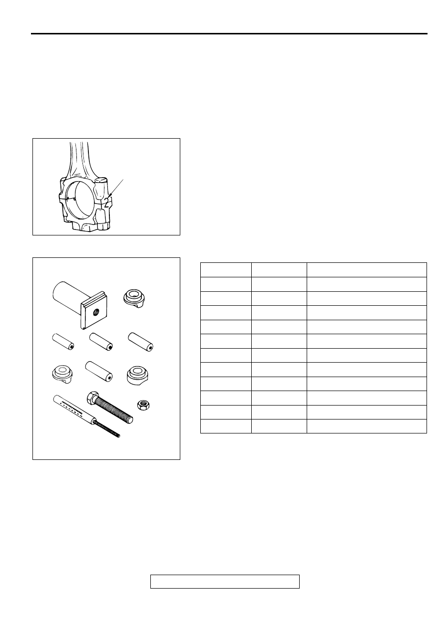
<<A>> CONNECTING ROD CAP REMOVAL
1. Mark the cylinder number on the side of the connecting rod 

big end for correct reassembly.

2. Keep the removed connecting rods, caps, and bearings in 

that order according to the cylinder number.

<<B>> PISTON PIN REMOVAL

1. Remove the stop screw from the base.

2. Select the correct piston support for your application (See 

above). Fit the piston support onto the base. Place the base 
on press support blocks.

10.PISTON
11. CONNECTING ROD
12.BOLT

REMOVAL STEPS (Continued)

AKX00600

CYLINDER NUMBER

AB

ITEM NO.

PART NO.

DESCRIPTION

1.

MIT310134

Base

2.

MIT310136

Piston support

3.

MIT310137

Connecting rod guide pin

4.

MIT310138

Connecting rod guide pin

5.

MIT310139

Connecting rod guide pin

6.

MIT310140

Piston support

7.

MIT310141

Connecting rod guide pin

8.

MIT310142

Piston support

9.

MIT48143

Press pin

10.

216943

Stop screw

11.

10396

Nut

AKX00598

PISTON PIN SETTING 
TOOL MIT216941

1

2

5

8

11

10

9

6

3

4

7

AB

PISTON AND CONNECTING ROD

TSB Revision

ENGINE OVERHAUL <2.4L>

11B-50

3. Insert the press pin through the piston pin hole. Select the 

correct connecting rod guide pin (See above). Thread the 
guide pin onto the threaded portion of the press pin.

4. Position the piston assembly on the piston support in the 

press. With the press pin up as shown, insert the guide pin 
through the hole in the piston and through the hole in the 
piston support.

CAUTION

To avoid piston damage, the piston support must seat 
squarely against the piston. Verify that the piston pin will 
slide through the hole in the piston support.
5. Press the piston pin out of the assembly.

6. Remove the piston pin from the press pin.

INSTALLATION SERVICE POINTS

>>A<< PISTON PIN INSTALLATION
1. Thread the stop screw and lock nut assembly into the base. 

Fit the correct piston support on top of the base. Insert the 
press pin, threaded end up, into the hole in the piston 
support until the press pin touches the stop screw.

2. Using the markings on the press pin, adjust the stop screw 

to the depth shown on the instruction for special tool 
MIT216941.

AKX00516

PRESS
PIN

PISTON PIN

FRONT MARK

FRONT
MARK

CONNECTING
ROD GUIDE PIN

BASE

AB

AKX00599

PRESS
PIN

BASE

PISTON
SUPPORT

LOCKNUT

STOP SCREW

FLAT PISTON 
SUPPORT

PIN DEPTH SET 
LOCATION

AB

PISTON AND CONNECTING ROD

TSB Revision

ENGINE OVERHAUL <2.4L>

11B-51

3. Place the base on press support blocks.

4. Slide the piston pin over the threaded end of the press pin, 

and thread the correct guide pin up against it.

5. Coat the piston pin with engine oil. With the connecting rod 

held in position, slide the guide pin through the piston and 
connecting rod.

6. Press the piston pin through the connecting rod until the 

guide pin contacts the stop screw.

CAUTION

Due to production tolerance variations, it is necessary to 
visually inspect the piston pin depth after installation to 
verify that the piston pin is centered. Adjust if necessary.
7. Remove the piston assembly from the base. Remove the 

guide pin and press pin from the assembly.

8. Check that the piston moves smoothly.

>>B<< OIL RING INSTALLATION
1. Fit the oil ring spacer into the piston ring groove.

NOTE: The side rails and spacer may be installed in either 
direction.

NOTE: New spacers and side rails are colored for 
identification of their sizes.

AKX00517

JAM NUT

PISTON PIN

PISTON PIN

FRONT
MARK

CONNECTING
ROD 
GUIDE PIN

BASE

STOP
SCREW

AB

AKX00568

SIZE

IDENTIFICATION COLOR

Standard

None

0.50 mm (0.020 in) oversize

Red

1.00 mm (0.040 in) oversize

Yellow

AKX00473

UPPER SIDE RAIL

LOWER SIDE RAIL

SPACER

AB

PISTON AND CONNECTING ROD

TSB Revision

ENGINE OVERHAUL <2.4L>

11B-52

CAUTION

Do not use a piston ring expander when installing side rail.
2. Install the upper side rail.

To install the side rail, first fit one end of the rail into the 
piston groove, then press the remaining portion into position 
by finger. See illustration.

3. Install the lower side rail in the same procedure as described 

in step 2.

4. Make sure that the side rails move smoothly in both 

directions.

>>C<< PISTON RING NUMBER 2 / PISTON RING NUMBER 
1 INSTALLATION
1. To prevent wrong installation, check the identification mark 

of each piston ring. The identification mark is stamped near 
the ring gap:

Identification mark:

Number 1 ring 1R
Number 2 ring 2R

NOTE: Size marks on piston rings are as follows.

2. Using the piston ring expander, fit number 2 into the number 

2 groove of piston.

NOTE: Install piston rings with identification mark facing up, 
to the piston crown side.

3. Install the number 1 piston ring in the same manner as step 

2.

AKX00442

SIDE RAIL END

AB

SIZE

SIZE MARK

Standard

None

0.50 mm (0.020 in) oversize

50

1.00 mm (0.040 in) oversize

100

AKX00527

NO.2

IDENTIFICATION MARK "1R"

IDENTIFICATION
MARK "2R"

SIZE MARK

NO.1

AB

AKX00515


Content   ..  40  41  42  43   ..